Brain Models Built From Timing Devices
An Eye for Sharp Contrast:
Visual Edge Detector and Focusing System
"An Eye for Sharp Contrast" is a system built out of timing devices — proposed technology that is presented on this site. Operations of the Eye model specific activity of the brain and eye of a rudimentary animal. The Eye has limited functionality. A chief purpose is to build a seed or point of origin for development of systems that have larger repertoires, as discussed in ( ... ) "Eyes That Look at Objects."
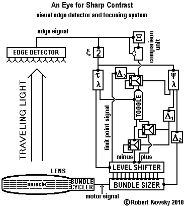
Overview and Chief Operating Principles. The Eye for Sharp Contrast detects an edge in an image and focuses on the edge. The Edge Detector has a linear array of photo-sensitive devices. An "edge" is detected as a large jump in the intensity of illumination along the array. Focusing means adjusting the force applied by the muscle that controls the focal length of the Lens of the Eye. The purpose of the adjustment is to sharpen the edge in the image, meaning to increase the jump in illumination intensity. Guided by signals from the Edge Detector, the Eye seek outs and maintains the sharpest possible image.
If the edge is produced by an object in the environment that moves nearer to or farther from the Eye, the Eye adjusts so as to continue to focus on the edge and maintain the sharpest possible image. Accordingly, the Eye follows movements of the object.
|
|
|
Contents
|
|
( ... )
|
1.
| The Eye is a Model of Sensory-Motor Activity
|
|
( ... )
|
2.
| Signal Generators from the Kit of Parts
|
|
( ... )
|
3.
| Sensory System (Edge Detector)
|
|
( ... )
|
4.
| Motor System (Level Shifter, Bundle Sizer, Bundle Cycler, muscle and Lens)
|
|
( ... )
|
5.
| Mathematical-Logical Linkage (comparison unit and Toggle)
|
|
( ... )
|
6.
| Operating cycles
|
|
( ... )
|
7.
| Remarks
|
|
( ... )
|
8.
| Link List
|
|
|
|
1. The Eye is a Model of Sensory-Motor Activity
This section surveys operating principles of the Eye for Sharp Contrast. Sections 2, 3, 4 and 5 describe the timing device modules that are used in the Eye and details of their operations. In section 6, a cyclical principle is used to organize and coordinate operations of modules. The Eye is a stage in development of general principles of timing device technologies, which are discussed in Section 7.
Timing device systems embody a principle of action. Please see the ( ... ) Opening Page, "Brain Models Built From Timing Devices" and ( ... ) "Timing Devices: a Kit of Parts," which is a prerequisite for this page. The Eye for Sharp Contrast models ongoing, continuous action, called sensory-motor activity, that coordinates perceptible sensations and muscular movements. Swiss psychologist ( ... ) Jean Piaget (1896-1980) showed that sensory-motor activity was the point of origin for development of intelligence in children.
Suppose that the Eye is part of a frog-like creature that is sitting on a riverbank and waiting for an insect to come within striking distance of its tongue. Perhaps the insect will perch on an overhanging branch or hover in the air so that the Eye can focus on it and guide the tongue muscles. Or suppose that the Eye is part of an aquatic creature that is preparing to bite a fin-like "edge" visible in the murky depths and to start chewing if possible. For such tasks, only minimal visual acuity is needed.
The Edge Detector has a linear array of light-modulated timing devices that resemble photo-sensisitive cells in an animal's eye. It generates the edge signal, which is characterized by a continuously variable frequency. A large jump of illumination along the line of light-modulated timing devices is detected as an "edge" and the larger the jump, the "sharper" the edge. A higher frequency edge signal means a sharper edge. An edge signal with a frequency above a threshold passes through the high pass filter (the device denoted by a "2") and starts (or maintains) operations of the two signal generators, one generating the short-period τ signal and the other generating the long-period ψ signal. In other words, if an edge-like feature appears in the visual field, the Eye will "turn on" and start operating.
While it is operating, the Eye attempts to "focus on the edge." The Motor System controls the strength of the force exerted on the Lens by the muscle. The focal length of the Lens changes as the muscular force varies. There is a minimum level of muscular force at which the Eye focuses on objects at a maximum distance. When the muscular force is stronger, the Eye focuses on objects that are closer. In this rudimentary design of the Eye, the level of force is controlled by the number of pulses in a pulse bundle that drives the muscle – the more pulses per bundle, the stronger the force. Only the number of pulses in a bundle varies: bundle organizational period ψ and signal period π are fixed. [Bundle specifications are discussed in the ( ... ) Kit of Parts page.]
The Eye operates through cycles of steps, with emphasis on linked changes. While the Eye is "on," the force applied by the muscle changes during each ψ-cycle. The size of a change is fixed but the change can occur in two different directions, with muscular force either becoming stronger or becoming weaker. The muscular force is "jittery," continually changing, getting stronger and weaker and stronger again; and the jitter is the means of adjustment and control.
Suppose we enter a ψ-cycle while a new motor signal is replacing a prior motor signal. The muscular force changes, and we note that the force becomes either stronger or weaker. Thus, the focal length of the Lens changes, causing a change in the image projected onto the Edge Detector. Then the "now" edge signal is compared to the "prior" edge signal that was detected during the previous cycle. The result determines the next change in the motor signal and muscular force. If the now edge signal has a higher frequency than that of the prior edge signal, denoting a sharper image, the next strengthening or weakening of muscular force is in the same direction as the prior force change just noted. The principle is: it worked before, so do it again. If, on the other hand, the now edge signal has a lower frequency than that of the prior edge signal, denoting a fuzzier image, the next force change reverses that of the prior change: if the prior step weakened the muscular force, the next step will make it stronger; and vice-versa. As the muscular force changes, we have completed one cycle. Cycling continues.
The Eye's stepwise changes seek out and tend to maintain the highest frequency edge signal that can be produced from the Edge Detector. The result is achieved through constant jittery muscular activity that is made up of overshoots and reversals.
If jittery muscular activity stays within a small fixed range, the average motor signal is a measure of distance to the object, which is presumed to be fixed in space. [In contrast, the edge signal, which corresponds to perceptible sensation, provides no guidance about distance.] The average motor signal can also track or follow the changing distance of a moving object if movement occurs slowly enough.
( ... ) top of page
2. Signal Generators from the "Kit of Parts"

|
|
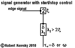
The Eye for Sharp Contrast includes two "signal generators with start/stop control." The generators and signals are denoted by τ and ψ. Each signal generator produces an ideal pulse train, that is, a stream of pulses with a fixed period between any two pulses. As discussed in the next section, each photo-sensitive device in the Edge Detector is part of a signal generator that produces a variable frequency pulse stream. The two kinds of signals are shown in the adjacent Figure. These signal generators are the sources of all signals within the Eye.
|
|
The adjacent Figure shows a "signal generator with start/stop control" from ( ... ) "Timing Devices: a Kit of Parts." The two-pulse device has a timing interval, ξ, that specifies the minimum frequency of a pulse train that generates an output signal. The two-pulse device operates as a high-pass filter, with a specification that is matched to the λ1 specification in the signal generators.
That is, when the frequency of pulses in the edge signal remains below 1/ξ, the signal generators are "off" or silent, a condition denoted by ω. If pulses in the the edge signal arrive faster than one every ξ, the two-pulse device produces a signal with half the frequency, which turns on the signal generators, if they are not on already.
|
|
|
The value of λ1 is set to be greater than 2ξ. Suppose λ1 is much greater than 2ξ and that the signal generators are running. The signal generators take a long time to turn off when the edge signal falls below the minimum frequency. As λ1>2ξ is reduced and gets closer to 2ξ, stopping becomes quicker. Design goals generally suggest that once a signal generator starts, it should remain in operation for a substantial amount of time, rather than having frequent starts and stops. Hence, a large λ1 — several seconds at least — may be desirable, resulting in prolonged operations of the eye even when there is nothing to focus on.
( ... ) top of page
3. Sensory System (Edge Detector)
Operating principle of the Edge Detector
Suppose that an opaque "test object" with a perfectly sharp edge is presented to the Eye in an optimal way so that half of the Eye's visual field is in the shadow of the object. Another possible test object is a particle-like "bug." The Eye should operate much the same for the two test objects.
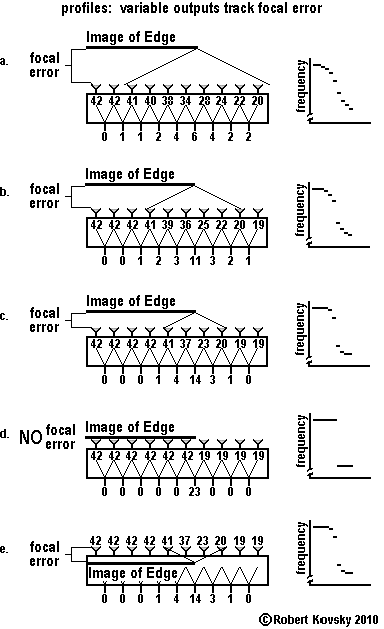
The Lens of the Eye projects an optical image of the object (and edge) onto the array of light-sensitive devices in the Edge Detector. If the object is exactly in focus, the image has a perfectly sharp edge, or nearly so. If the object is not exactly in focus, the image of the edge spreads out, with more spreading as the deviation from exact focus increases.
The Edge Detector converts the optical image into the edge signal that measures the sharpness of the edge in the image. A perfectly sharp object is not required so long as an image is formed that generates an edge signal. Two images can be compared as to greater or lesser sharpness by means of the edge signal. The highest edge signal means the maximum sharpness means the best possible focus.
The Figure below shows how a perfectly sharp object can generate different images with a varying degree of sharpness depending on a varying focus of the Lens. There is an error in focusing, called focal error. Operationally, focal error is reduced by adjusting the focal length of the Lens. The sharper the edge, the less the focal error. The same principle applies to objects with edges that are less than perfectly sharp.

Construction Details of the Edge Detector:
Sensory Layer and Differentiation Layer
The Edge Detector is made up of four Layers and each Layer is made up of repeated units that connect to each other in "tiled" patterns — that is, repeating unit patterns that are connected together in a continuing way. "Tiling" is a chief organizing principle of timing device designs. The Edge Detector illustrates how tiled assemblies of timing devices can generate meaningful signals.
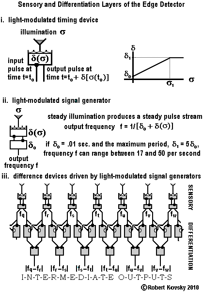
For clarity of presentation, a particular numerical example is used, in which the primal responding period δ0 = 0.01 sec. That is, constructions are based on a ( ... ) primal timing device, which responds to an input pulse by discharging an output pulse 1/100 of a second later. The primal refractory or resting period is β=1/1000 of a second. All timing device operations in this design of the Eye are based on this single set of primal timing intervals. Primal timing intervals are modified to accommodate specific needs and purposes of particular modules.
Examining the device design in closer detail, sensory input originates in a light-modulated timing device shown below in Figure i. The light-modulated timing device is part of a light-modulated signal generator shown below in Figure ii. Such devices and generators are discussed in detail in the ( ... ) Kit of Parts page.
|
|
When a light-modulated timing device is "in the dark," it acts the same as a primal timing device -- δ = δ0 = 0.01 sec. -- and the signal generator produces a stream of of 50 pulses per second. When the light-modulated device is "fully illuminated," the modulated δ = δ1 = 0.05 sec. and the signal generator produces a pulse stream at the rate of 17 per second (rounding within the limit). When illumination is between the extremes, the signal generator produces a pulse stream with a frequency that is intermediate between the extremes and that measures the illumination.
Light-modulated signal generators are organized in the Sensory Layer shown in Fig. iii, where light-modulated signal generator ϑ produces a pulse stream with a frequency, fϑ. The Sensory Layer provides signals to the Differentiation Layer, which then produces Intermediate Output signals.
In device-based "differentiation," signals from neighboring sensory-modulated signal generators are input signals into ( ... ) "balancing units." Outputs from the balancing units carry the Intermediate Output signals that then pass into the third and fourth layers of the Edge Detector.
|
An Intermediate Output signal is a "difference signal" in which pulses occur periodically with a frequency that, on average, is the difference between the two input frequencies, e.g., fs – ft. The absolute value signs – "|...|" – change any negative number into a positive number equal in size.
Construction Details of the Edge Detector:
Selection Layer and Collection Layer
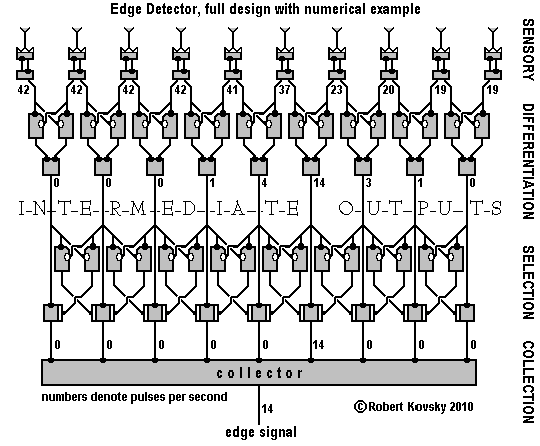
The Selection Layer and Collection Layer are the third and fourth Layers of the Edge Detector. The entire Edge Detector is shown in the Figure below, which includes the Sensory Layer and Differentiation Layer previously discussed.
The Selection Layer "passes" the Intermediate Output signal with the maximum frequency and "blocks" all other Intermediate Outputs. The Intermediate Output signal that is passed becomes the edge signal.
The selection function is performed through balancing units, each driven by signals of two neighboring Intermediate Outputs. For each two adjacent Intermediate Outputs, the balancing unit will generate a signal that blocks the passage of the lower frequency output signal.
Performance of the selection function is shown with a single maximum but there is tolerance for variations, e.g., for a "double maximum" based on a single object in the environment such as a bug that casts a shadow onto a bloc of 4 or 5 photo-sensitive devices. The principle is that operations depend on changes between cycles rather than on a single value that occurs during a particular cycle.
The "many-to-one" Collection Layer is a single, simple, spatially extended timing device — the "collector" — that has multiple inputs and a single output, which carries the edge signal. In the "single maximum" exemplar in the Figure, only one input is active at any one time and that input generates the edge signal.
[Balancing units are discussed in the ( ... ) Kit of Parts page. For a clearer Figure, a slightly modified "two-sided" symbol for the gate normally open timing device has been introduced (original at ... ). There is no operational difference.]
( ... ) top of page
4. Motor System (Level Shifter, Bundle Sizer, Bundle Cycler, muscle and Lens)
Discussion of the Motor System starts with the working end. Muscle fibers encircle the Lens like an elastic girdle. The "caps" of the Lens protrude outward from the girdle. When the girdle is loose, the Lens is relatively flat and the focus is at the greatest distance. When the girdle tightens, squeezing the Lens, the caps of the Lens protrude further outward, rounding the Lens and shortening its focal length.
The "motor signal" controls the muscle that encircles the Lens. First the motor signal is discussed. Next, the discussion shows how the motor signal squeezes the Lens and thus controls the focusing of images. Then the discussion traces generation of the motor signal backwards towards the Toggle, which is part of the Mathematical and Logical Linkage. The following section shows how the Linkage connects the Motor System with the Sensory System previously described.
Motor signal
The signal in the Figure below illustrates the motor signal. More pulses in a bundle mean a stronger muscular force squeezing the Lens.
While the Eye is active, the number of pulses in a motor signal bundle changes by one between successive bundles. Leading pulses in successive bundles are separated by the period ψ. The signal period between pulses in a pulse bundle is a fixed amount, π.
For the numerical example, π = δ0 = 0.01 sec. The least squeezing is produced by a pulse bundle that has 3 pulses and the most squeezing is produced by a bundle that has 14 pulses. There are 12 levels of squeezing and the Lens can have any one of 12 fixed focal lengths. The Lens shifts between levels at the rate of one step per ψ cycle, with ψ = 48 δ0, ψ = 64 δ0 or ψ = 80 δ0. The Eye takes some 7 to 11 seconds to traverse its range of activity. The limited repertoire and slow speed of the Eye call out for improvement, such as improvements suggested in ( ... ) Eyes That Look at Objects.
Bundle Cycler, muscle, muscle fibers and attachments
The Figure below shows the Bundle Cycler and part of the array of muscle fibers that girdle the Lens. The Figure also shows pulse patterns and resulting muscular forces that contract the muscle fibers, thus squeezing the Lens and controlling its focus. Muscle fibers and forces are discussed in ( ... ) the Kit of Parts page.
Each muscle fiber is driven by a signal on the line directed to it from the Bundle Cycler. Each bundle in the signal is a duplicate of a motor signal bundle; but bundles on different lines have different relative time displacements. The effect of the organization of time displacements is that the Eye can maintain a fixed focus, more or less, and can also change a focus smoothly, more or less. Four muscle fibers are attached to a single point of attachment (shown in dark gray). The effect is that overlapping and rotating twitches of uniform force and duration will result in a pulling of attachments (and squeezing of the Lens) that is approximately constant. The Lens, an elastic material body, is presumed to somewhat smoothe the wobbles that are generated by pulsational squeezing. More fibers and more complex interweaving will result in better constancy and smoother operations.
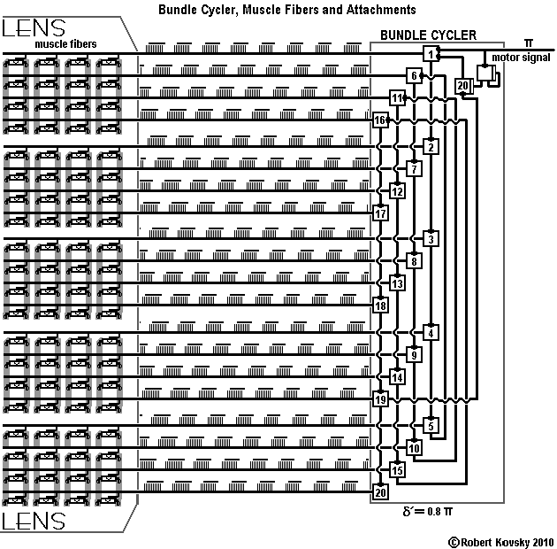
The flow of activity starts at the upper-right hand corner of the Figure where the motor signal enters. The motor signal has a long period of silence between bundles. Duplicate copies of the most recent motor signal bundle are sent to muscle fibers while the motor signal is silent. For the numerical example, pulse bundles in the motor signal last between 2 δ0 (three pulses) and 13 δ0 (fourteen pulses). For the case where ψ = 48 δ0, shown in the Figure, the silent period in the motor signal is 32 δ0, 2/3 of the organizational period, ψ. The Bundle Cycler "fills in" each long silent period in the motor signal with two copies of the prior motor signal bundle.
Detailed operations of the Bundle Cycler are based on the circular loop of 20 simple timing devices, each with a responding period δ' = 0.8 δ0. Pulses in the motor signal have a period π = δ0. Devices discharge in the order indicated by numbers in the schematic icons. The loop can hold a signal that lasts 16 δ0. Bundles in the numerical example fit within the loop. As a pulse bundle passes through a timing device in the loop (or the isolated device 20), the bundle activates the corresponding muscle fiber.
Suppose a pulse bundle is circulating in the Bundle Cycler and the motor signal falls silent. The pulse bundle will continue circulating without limit. Identical bundles will be distributed to all the muscle fibers and the Lens will maintain a fixed focal length. When the motor signal appears, it interrupts the cycling by closing the gate in the return link numbered 20, where the timing device has a normally open gate. Then the new bundle from the motor signal activates the loop, replacing or superseding the existing bundle.
In other words, during 2/3 of the ψ-cycle used in the Figure, the bundle in the Bundle Cycler is repeating. During 1/3 of the ψ-cycle, the size of bundles is changing by one pulse per bundle. Hence, signals sent to a muscle fiber are made up of a pair of repeating bundles alternating with a change in bundle size. The alternating activity occurs in the form of "—change—steady—steady—change—steady—steady—change—steady—steady—" and so forth. (The ψ = 64 δ0 period has triplet "steady" bundles for every "change" bundle, etc.)
For successful operations, timing intervals must satisfy certain constraints. For this design, the period between pulses, π = δ0. A timing device in the 20-device loop must respond to every pulse; hence, δ' and β' must satisfy the constraint δ' + β' < π. This constraint is similar to that involving the "signal generator with coupled drivers" discussed in ( ... ) Timing Devices: a Kit of Parts.
The two gate normally open devices have modulation periods λ = 14 δ0. When a new pulse bundle in the incoming motor signal passes through the first gate normally open device, the bundle is reduced to a leading pulse. That leading pulse then triggers the second gate normally open device (the final device in the 20 device loop), which blocks re-cycling of the bundle then in the Bundle Cycler. The new pulse bundle and the re-cycling pulse bundle are identical for the first three pulses, so no problems arise from the first one or two pulses of both signals arriving at the same time.
Bundle Sizer
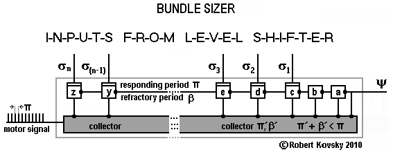
The Bundle Sizer shown in the Figure below generates the pulse bundles in the motor signal. The ψ pulse triggers the large gray collector timing device, which responds by discharging the leading pulse in a motor signal bundle. The ψ pulse also triggers the timing device labeled a, which responds and thus triggers both the collector and timing device b, starting a pulse wave. The pulses triggering the collector are separated by the responding period π that is shared by the lettered timing devices in the module. The pulse wave passes down the line of the lettered timing devices through b and even further, perhaps to z. A signal on a σ line closes the gate of a lettered device and terminates the pulse wave and the pulse bundle.
The collector resembles the single many-to-one device in the Collection Layer of the Edge Detector discussed above. The responding period and refractory period of the collector are small enough that the collector returns to the ready condition between discharges of devices a through z. That is, π' + β' < π.
During operations, exactly one of the σ inputs into the Bundle Sizer is active. Suppose that the active input is σ3. The gate will close in the gate normally open device e. Neither e nor any later gate normally open device will discharge; and the pulse bundle generated by the collector will end after 5 pulses.
Level Shifter
The Level Shifter, shown in the Figure below, provides exactly one active σ output for the Bundle Sizer. That is, the τ signal that arrives as input to the Level Shifter from the signal generator passes through the module and generates an output signal at a single level j so that σj is the active output. An output signal from the Level Shifter controls the size of pulse bundles generated by the Bundle Sizer as previously discussed.
The function of the Level Shifter is to change the level of the active output signal once each ψ cycle. This function is performed by the arrival of an input "shift pulse" through either the plus line or the minus line. The sequence of events is that, first, a shift pulse arrives at the Level Shifter through either the plus line or the minus line, then the output level shifts up one if a plus pulse has arrived or the output level shifts down one if a minus pulse has arrived. If the level is at the end of the range of activity, a pulse is delivered through the "limit point reversal" line that goes to the Toggle. As described below, the Toggle will make the next shift pulse the opposite of the one just received.
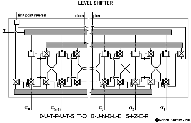
Inside the Level Shifter, the τ input signal to the gray "distribution device" (a one-to-many device resembling a collector except that it operates in the opposite direction) generates duplicate signals to all of the gate normally open devices. All of these normally gate open devices are generating duplicate pulse trains except during shifting when the one active output is interrupted by closure of the open gate in that branch.
Suppose σ2 is the active output. The normally closed device generating the output is keeping its own gate open and it is also keeping open the gates in two adjoining gate normally closed devices that are connected to the plus and minus distribution devices (also shown in gray). Suppose a plus pulse arrives at the lower distribution device. That pulse will trigger the gate normally closed device between the σ2 and σ3 outputs where the gate is being kept open. That is the only gate normally closed device activated by the plus pulse. When that device discharges in response, the output pulses will both interrupt the σ2 gate normally open device, leading to a cessation of the σ2 signal, and also close the gate in the σ3 output gate normally closed device, which then becomes active and stays open. This complete the shifting of level from level 2 to level 3.
Suppose that the plus line is continually active. The level keeps shifting up until it comes to level n at σn. Then the next plus pulse sends a signal on the "limit point reversal" line. This pulse will change the active plus line to an active minus line through action of the Toggle, which is discussed in the next section.
The foregoing operations involving an active plus line are mirrored by symmetrical operations involving an active minus line.
( ... ) top of page
5. Mathematical-Logical Linkage (comparison unit and Toggle)
The Motor System and the Toggle can operate on their own without input from the Sensory System so long as the signal generators are running. Such operations can occur by "jamming open" the two-pulse device that acts as a high-pass filter while leaving the Edge Detector wholly in the dark. During such operations, the shift pulse is repeatedly plus or repeatedly minus so that the Level Shifter runs to the end of its range; then, a limit point signal is sent from the Level Shifter to the Toggle, reversing the shift pulse so that the Level Shifter runs in the opposite direction towards the other end of its range. The activity runs back and forth and is called "full-ranging."
Full-ranging activity of the motor system of the Eye can also be interrupted and controlled by signals from the comparison unit that are sent to the Toggle. Signals to the Toggle from the comparison unit have their origins in the edge signal, discussed above. Control through interruptions is characteristic of the Eye for Sharp Contrast, e.g., as discussed above in connection with the Bundle Cycler and Bundle Sizer.
Toggle
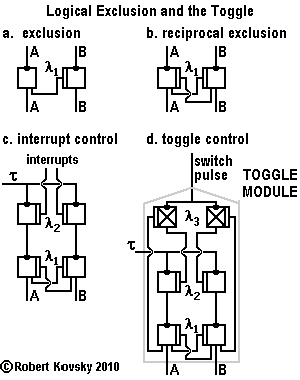
The Toggle embodies the principle of "exclusion," shown in a simple form in Figure a below. When signal A is active, pulses from A close the gate in device B and the output signal from B is blocked or excluded.
The complete Toggle module is shown in Fig. d. There are two output lines marked "A" and "B" that are directed towards the "plus" and "minus" inputs to the Level Shifter. The input τ signal appears as active output on either the A line or the B line; and the other line is silent. Which output line is active and which is silent is subject to change. A "switch pulse" changes the active output line. The action resembles toggle activity of electrical switches and/or logical flip-flops. One output pulse is lost during the change-over. All the timing devices in the Toggle module have a common δ and β.
|
|
Fig. b shows an intermediate step in the construction. Suppose signals are active at both the A and B inputs. There are two equal but distinct branches in a reciprocal relationship. The active output from one branch silences output from the other branch. The active/silent split can be maintained with either branch as the active branch. This is reciprocal exclusion similar to the "exclusive or" relation in logic or "either-or" in common experience.
Operations involving reciprocal exclusion can take place in different ways. Suppose both inputs are silent and then both become active but at different times. The first input to become active "seizes control" for that branch and blocks output from the other branch.
Or suppose both inputs are running and branch A is in control. If input A is "interrupted" while input B continues running, B will seize control and hold control even after A has returned to activity.
Fig. c shows development of the reciprocal exclusion arrangement to provide for interrupt control. A pulse through one interrupt line interrupts the signal in the targeted branch but not in the other branch. If side A is in control, a pulse through the interrupt line on the A side will switch control to B.
Fig. d, the final Toggle Module, provides for automatic routing of a switch pulse. The switch pulse passes through the gate normally closed device where the gate is kept open by the active output; hence the pulse interrupts the active output. The branch with the inactive output is not affected by the interruption and thus seizes control.
|
The comparison unit
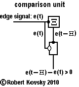
The comparison unit provides a signal to the Toggle that interrupts and reverses full-ranging activity of the Eye's Motor System as previously discussed.
|
The comparison unit is made up of a ( ... ) difference device and a ( ... ) bundle storage device, both discussed in the Kit of Parts page.
Ξ is set equal to ½ of ψ. This value is chosen so that the changing part of the present cycle is compared to the steady part of the prior cycle. For the case where ψ = .48 sec., the bundle storage device is a string of 24 primal timing devices, each with a responding period of δ0 = 0.1 sec.
|
|
|
Let the frequency of the edge signal be denoted by e(t). The signal that comes out of the bundle storage device has a frequency e(t – Ξ). The frequency of output pulses from the difference device is equal, on average, to e(t – Ξ) – e(t) if that number is greater than 0; otherwise, the output is silent. The presence of an output signal means that the frequency of pulses in the edge signal is smaller than it was in the prior cycle.
( ... ) top of page
6. Operating Cycles
Operations of individual modules have been discussed in preceding sections. In this section, individual operations are organized to make up operations of the system. The organizing principle is the ψ cycle of changes. Three specifications for ψ are considered: ψ = 48 δ0, ψ = 64 δ0 and ψ = 80 δ0.
During each ψ cycle, regardless of size, distinct changes in pulse patterns occur in each of the modules, except for the signal generators. Changes in one module are linked to changes in a successor module and successive links form a circle of modules, with one link made up of light and shadow. There is also a cycle in time. These are aspects of a circulating flow of changes that can be described at each point by relations such as "predecessor change and successor change." Circulating changes perform the functions of the Eye, namely, the functions of detecting and focusing on an edge (sharp contrast) in the visual field.
The ψ-cycle divides into four stages. Activities and changes in the first three stages are exactly defined, within forms of the technology. Changes in the fourth stage are more difficult to define because "concurrent" changes occur in multiple interconnected modules during overlapping time periods and changes vary according to particular circumstances in complex ways.
Discussion begins with an overview of the whole cycle, identifying separate stages and changes that occur in particular modules in the context of the whole cycle. A "standard for successful performance" is stated. Next, operations are discussed in detail, using the ongoing numerical example. For the case where ψ = 48 δ0, operations would appear to fail to achieve successful performance except on relatively few occasions. During slower operations, where ψ = 64 δ0, successful performance would appear to be more consistent but still subject to lapses. For the slowest case where ψ = 80 δ0, consistent successful performance should be expected.
|
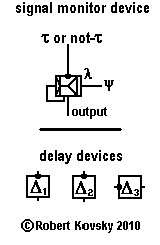
Two simple devices from the Kit of Parts are involved in the operating cycle, namely a ( ... ) signal monitor device and ( ... ) delay devices, shown in the adjacent Figure.
The signal monitor device detects whether there is a signal on the trigger input line. It is a gate device where the gate is opened by a ψ pulse. The gate can stay open for the whole modulation interval λ but it closes immediately after a single trigger input pulse generates an output pulse. That is, if a single τ input pulse arrives during the modulation period, an output pulse will be generated. Any additional τ input pulses prior to the next ψ pulse are blocked and have no effect on later activities.
Delay devices are used in the Eye to control the sequencing of events. The ψ pulse activates or triggers changes in modules at different points in the cycle, as specified by the amount of delay in delay devices. Each delay device interposes a fixed amount of delay, like a fixed resistance in electronic circuits. A delay device is used to delay a single pulse, not a pulse train or a pulse bundle.
|
|
|
The whole ψ cycle
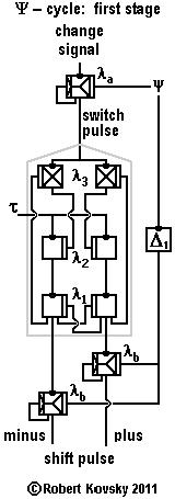
The ψ cycle is controlled by the ψ signal generator and the generator's instant of discharge is the most convenient point to enter the ψ cycle, at the beginning of the first stage of operations. The ψ pulse opens the gate in the upper signal monitor device that precedes the Toggle in the cyclical flow of changes. The modulation period of the upper signal monitor is a large quantity, namely, λa = W, the "waiting period," which is the maximum period for the upper signal monitor to respond to a signal from the comparison unit.
The upper signal monitor device is waiting for a pulse that is generated from activity that occurred during the prior cycle. One possible source of such a pulse is a limit reversal signal and the other possible source is a pulse from the comparison unit . The size of the delay Δ3 is more than half that of ψ, so that a limit reversal pulse, if one is generated, arrives at the upper signal monitor during the waiting period of the next ψ cycle. Any output signal from the comparison unit is based on activity occurring during the prior cycle. A pulse generated during the prior cycle, either a limit reversal pulse or a pulse from the comparison unit, triggers the upper signal monitor. If the upper signal monitor is triggered, it discharges a "switch pulse" that activates the Toggle and switches the active and inactive output lines of the Toggle. If no signal arrives at the the upper signal monitor during the waiting period, the Toggle does not switch.
Whether the Toggle is switched or unswitched has consequences that extend to the Level Shifter and through to the muscle. During the previous cycle, activity in the Level Shifter shifted, either in the plus direction or in the minus direction. If the Toggle is unswitched, the next shift will be in the same direction as occurred during the prior shift. If the Toggle is switched, the next shift will reverse the prior shift and move in the opposite direction.
The waiting period W is incorporated in the value of Δ1 that sets the activation instant for the lower signal monitor devices. Also incorporated in the value of Δ1 is the period of time required for the Toggle to operate and complete the switch between outputs, if there is switching. The value of Δ1 is a fixed quantity and sets a clear marker.
Discharge by the Δ1 delay device marks the beginning of the second stage of operations of the ψ cycle.
After activation of the lower signal monitor devices by the Δ1-delayed ψ pulse, a shift pulse is discharged on either the minus line or the plus line, leading to a shift in the σ level of the Level Shifter.
The value of Δ2 in the corresponding delay device specifies the instant of generation of the leading pulse of the motor signal. That is, the pulse discharged by the Δ2 delay device arrives at the Bundle Sizer and immediately triggers the leading pulse in the new pulse bundle in the motor signal. The delayed ψ pulse also starts a pulse wave in the Bundle Sizer that is timed to arrive at the first controlled timing device (timing device c in the ( ... ) Bundle Sizer design) after completion of shifting of the σ input level.
Like Δ1, Δ2 is a fixed quantity and serves as a clear marker. Discharge by the Δ2 delay device marks the beginning of the third stage of the ψ cycle.
During the third stage, the Δ2-delayed ψ pulse arriving at the Bundle Sizer generates the new motor signal pulse bundle, which enters the Bundle Cycler and generates waves of pulse bundles that stimulate fibers in the muscle. Because of the long loop in the Bundle Cycler, this stage is prolonged; and a period of 16 δ0 is required for the new motor signal bundle to reach all the muscle fibers.
In the fourth stage of the ψ cycle, overlapping with the third stage, progressive changes in illumination reach the Edge Detector. Illumination change occurs over a period of 16 δ0 concurrently with new motor signal activation of muscle fibers. Changes in illumination cause changes within the Edge Detector and its output, leading to concurrent changes in the edge signal and concurrent changing activity of the comparison unit. The comparison unit compares the changing edge signal with the edge signal that was received before the change started. The comparison unit discharges pulses when the comparison shows a declining edge signal frequency. If a single such pulse is discharged during the waiting period of the next cycle, a switch pulse is sent to the Toggle.
The ψ cycle under examination has now run its course and the next ψ cycle is underway.
Standard for successful performance of the Eye for Sharp Contrast.
Of course, all constructions are imaginary. Notwithstanding limitations of imagination, it appears possible to define a standard for successful performance of operations of the Eye for Sharp Contrast and to consider how different values for operating specifications (e.g., ψ = 48 δ0, ψ = 64 δ0 and ψ = 80 δ0) might lead to worse or better performance.
As discussed above, the Motor System and Toggle can operate without input from the Sensory System and such operations involve full-ranging activity. The Sensory System causes the discharge of pulses from the comparison unit, interrupting the Motor System's full-ranging activity and reversing the direction of shifting. Such sensory-based interruptions and reversals, when appropriate, constitute successful performance of the Eye's function of detecting and focusing on an edge. Failure occurs when the edge signal passes through a maximum in frequency but without causing a switch of the Toggle. Then full-ranging activity runs to the end of the range.
The Figure below shows a test in a controlled laboratory environment that enables the Eye to provide its best performance. Initially, the visual field is empty and the signal generators are set into action with a long λ period so they don't turn off during experiments. At time t = 0, a perfectly opaque object with a perfectly sharp edge is inserted into the environment in a position that is "on axis" with the Lens so that the object casts a shadow on the linear array of photo-sensitive devices in the Eye as described above. Each of the 12 levels in the Level Shifter denoted by σj corresponds to a "projected σj distance" from the Lens where an object would be in best or sharpest focus. The Eye has a "field of vision" that is defined by sharp focus at the endpoints of its range of shifting. An object with a sharp edge placed anywhere in the field of vision will lead to focusing activity as to the object. The object becomes an environmental "attachment" for activity of the Eye.
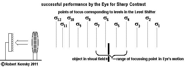
Successful performance of the Eye begins with full-ranging activity of the Motor System prior to the introduction of the object. The focal length of the lens enlarges and shrinks. Suppose that, when object insertion occurs, the focal length of the Lens is changing so that the edge of the shadow grows sharper. (If not, reversal soon occurs.) "Full-ranging" shifting in the Motor System continues while the shadow grows sharper. At a certain point, however, the shadow becomes fuzzier or less sharp. At that point, the comparison unit generates output that becomes a switch pulse. Full-ranging activity is interrupted and reversed. Because of the reversal, the image grows sharper again. It is almost like a return to full-ranging activity. But this lasts for only 1 or 2 cycles. Then another switch pulse interrupts and reverses the direction of shifting. After one or two cycles in the other direction — another interruption and reversal occur. And so forth.
During successful performance of the Eye, the object in the visual field generates repeated interruptions and reversals of direction of shifting in the Eye's motor system. The Level Shifter cyclically moves back and forth over four levels roughly centered around the projected distance of the object. The extent of shifting (number of levels) is reduced for objects near endpoints of the field of vision where limit point signals are the source of interruptions and reversals.
Motion of the object
Immobility of the object in the visual field has been implicit in the previous discussion. Two kinds of object motion are possible for the Eye: (1) motion where the edge travels along the linear array but staying the same distance from the Lens, called "transverse motion;" and (2) motion where the edge get closer to or farther from the Eye, moving perpendicular to the Lens, called "radial motion."
Operations of the Edge Detector are probably subject to a high rate of failure during transverse motion of the object. This is because the illumination profile at the sensory devices would change over the lengthy waiting period and Intermediate Outputs would vary in a wobbly way. The variance could generate output from the comparison unit even when sharpness is increasing, resulting in an erroneous reversal. Detection and following of movement of an object in a transverse direction is to be explored in ( ... ) Eyes That Look at Objects.
The Eye should perform successfully if the object is in radial motion, if the motion of the object is sufficiently slow. Such successful performance is "following" activity that is a chief goal of the construction. Suppose that the Eye is enlarging the focal distance through cyclical shifts (progressively greater j numbers) and that the object is moving towards the Eye at the rate that is less than one projected σj division per ψ cycle (progressively smaller j numbers). Successful performance requires the Eye to detect the edge and generate output from the comparison unit when the edge signal takes the equivalent of two steps away from the peak of sharpness in a single cycle. The Eye should be able to satisfy this requirement. Faster motion become problematic. The task is easier when the object is moving away from the eye. Symmetrical operations occur when the Eye is shortening the focal distance through progressively smaller j operations.
Detailed operations
Numerical example and commencement of the ψ cycle
In the numerical example, τ = 1.2 δ0; π = δ0; δ' = π' = 0.8 δ0; and β = β' = 0.1 δ0. Three cases are examined: ψ = 48 δ0, ψ = 64 δ0 and ψ = 80 δ0. The ψ cycle commences at the instant the ψ signal generator discharges a pulse. Operations are based on δ0 = 0.01 sec.
The waiting period
Immediately on discharge, the ψ pulse opens the gate in the upper signal monitor device. While the gate is open, the signal monitor is responsive to any output signal from the comparison unit and also to any limit reversal signal. If a pulse arrives on either line, the signal monitor device discharges a switch pulse that activates the Toggle. The value of λ = W, the "waiting period" for the signal monitor, fixes the minimum frequency signal from the comparison unit that is detected with assurance. This is an important specification because it sets the sensitivity of the Eye. Insensitivity is a chief cause of failure.
Review of the profiles of signals discussed above suggests that 6 pulses per second is a borderline choice for a detectable change in the edge signal. This requires about W = 17 δ0 = 0.17 sec. for assured detection. For greater sensitivity, such as detectable output from the comparison unit at the rate of 3 pulses per second, assured detection requires W = 33 δ0. The former figure is close to that of W in the case where ψ = 48 δ0 and the latter figure is close to W in the case where ψ = 64 δ0. The difference between the two values of ψ, 16 δ0, goes into the waiting period. When ψ = 80 δ0, the waiting period is increased to 0.5 sec. and the system is sensitive to an output of 2 pulses per second.
To facilitate the comparison, the value of W is carried as a variable in calculations.
Calculation of Δ1
The first stage of the ψ-cycle starts when the ψ signal generator discharges a pulse. The upper signal monitor "waits" for an output signal from the comparison unit or for a limit point signal; either of these signals provides a "change signal," shown in the Figure below. A change signal triggers the signal monitor to discharge a switch pulse that activates the Toggle. After the Toggle switches — or not — the Δ1 delay device discharges a pulse, activating the lower signal monitors, one of which responds by discharging the "shift pulse" to the Level Shifter. Discharge of the Δ1 delay device starts the second stage of the ψ-cycle.
We want to calculate the smallest value of the delay Δ1 such that the sub-system performs its intended function of switching between minus and plus shift pulses when a change signal is received. To start, at t = 0, the ψ signal generator discharges and activates the upper signal monitor. The gate on the upper signal monitor remains open for the modulation period, λa, the waiting period discussed above, denoted by "W."
|
Suppose that the comparison unit discharges a single "test pulse" at the last moment of the waiting period W. If the system performs successfully in handling such a test pulse, it will perform successfully in handling a pulse from the comparison unit no matter when the pulse appears during the waiting period. This is because the lower signal monitor devices are activated at the same point in each ψ cycle, specifically, at t = W + Δ1, no matter when the Toggle switches during the waiting period. If a change signal arrives early in the waiting period, the Toggle will switch that much earlier but operations of the lower signal monitor devices will not vary.
Inside the Toggle, the test pulse arrives at the λ3 gated normally closed devices at t = W + 1 and triggers the gate device where the gate is kept open by an output stream. The resulting pulse closes a λ2 gate at t = W + 2.
In general, ψ/τ is not an integer and τ pulses cannot be synchronized with ψ pulses. The period of τ pulses is 1.2 and the first τ pulse to be blocked by the closed λ2 gate arrives at the Toggle at some instant between t = W + 2.0 and t = W + 3.2, or, introducing a notation, when t = W + (2.0, 3.2).
Duplicate streams of τ pulses enter the two internal branches of the Toggle. Sometimes one stream is blocked, sometimes the other. Synchronization between the two streams continues when switches occur, even though some pulses never reach the output.
An output pulse from the λ1 gate device excludes the next pulse from the other output branch. The period between τ pulses is 1.2 and the responding period of the λ1 gate devices is 1.0; hence, λ1 must be greater than 0.2 to perform successfully. λ1 = 0.3 is satisfactory.
When switching occurs, the τ pulse that arrives at t = W + (2.0, 3.2), after closure of the λ2 gate, is blocked in both branches, at different points in the different branches. The last pulse to be discharged from the branch being switched off arrives at t = W + (0.8, 2.0) and is discharged 2.0 later, at t = W + (2.8, 4.0) . In the branch being switched on, the τ pulse that arrives at t = W + (3.2, 4.4) leads to the discharge of the first pulse in the newly active branch of the Toggle at t = W + (5.2, 6.4).
|
|
Therefore, for successful performance, the gate on the lower signal monitor opens just before t = W + 5.2 and closes just after t = W + 6.4. With these values, if the Toggle switches, the first switched Toggle output pulse triggers the corresponding lower signal monitor device to discharge the shift pulse. If the Toggle does not switch, a duplicate pulse arrives at the "same old" lower signal monitor device at the same time point.
A specific value is Δ1 = W + 5.1. A specific value for λb is 1.4.
Calculation of Δ2
The lower signal monitor device has a primal responding period of 1.0. Therefore, the shift pulse arrives at the Level Shifter at t = W + (6.2, 7.4). It is sufficient to specify operations for a shift pulse that arrives the Level Shifter at t = W +7.4. Earlier shifting does not change the generation of the motor signal.
The τ signal generator sends synchronized pulse streams to the Toggle and the Level Shifter. Operations in the Toggle, as discussed above, are based on a τ pulse that is generated at t = W +3.2. and that triggers a sequence of events leading to the arrival of a shift pulse at the Level Shifter at t = W +7.4. Successive τ pulses are generated at t = W +3.2, 4.4., 5.6, 6.8, 8.0 and 9.2 and become another input to the Level Shifter. The two inputs interact to produce the result.
Inside the Level Shifter, an arriving τ pulse triggers the discharge of a σ output after passing through the τ distributor and two gate timing devices; each device has a responding period of 1.0.
Also, 12 duplicate streams of τ pulses are discharged from the distributor at t = W +7.8, 9.0 and 10.2. When a shift takes place, a duplicate pair of pulses are discharged as σ outputs to the Bundle Sizer at the pivotal moment. Prior to the pivotal moment, output was on one σ line; after the pivotal moment, output is on the other σ line. (Duplicate pulses at the pivotal moment in the Level Shifter contrast with missing pulses at the pivotal moment in the Toggle.)
If the shift pulse arrives at t = W + 7.4, the gate configuration inside the Level Shifter changes at t = W + 9.4. The τ pulse that arrives at the Bundle Sizer at t = W +7.8 is discharged from both σ outputs at t = W + 10.8. The new σ level thereafter discharges pulses with the τ period of 1.2.
Inside the Bundle Sizer, the active σ input must maintain gate closure of the affected gate normally open device and, therefore the λ for the gate must be in excess of 1.2, say λ = 1.3. Hence, the pulse wave generated by ψ pulse (after a delay of Δ2), should arrive at the trigger junction of the timing device "c" no earlier than t = W +12.1, which is 1.3 after the arrival of the last σ1 pulse. (The shift from σ1 to σ2 is the shift that requires the largest Δ2 to work successfully.) The Δ2 - delayed ψ pulse arrives at the Bundle Sizer at 10.2; hence, it arrives at timing device "c" at 12.2, sufficiently late to accommodate the shifting of levels. That is, Δ2 = W + 10.2.
Third and fourth stages.
The ψ pulse, delayed by Δ2, arrives at the Bundle Sizer at t = W + 10.2 and triggers the leading pulse in the motor signal that arrives at the Bundle Cycler at t = W +11.0 and at the first muscle fiber at t = W +11.8. The Collector in the Bundle Sizer and timing devices inside the Bundle Cycler have a responding period (π' and δ') of 0.8 δ0.
Arrival of the leading pulse in the motor signal at the Bundle Sizer activates the third stage of the ψ-cycle. The third stage continues until the new motor signal bundle is stimulating all muscle fibers. For the leading pulse, this requires 1.6 δ0 in the Bundle Sizer and the first timing device in the Bundle Cycler. Then the bundle passes through the Bundle Cycler during the the next 16 δ0. Thus the third stage occupies that part of the ψ-cycle that extends from t = W +13.6. to t = W +29.6. By the end of this period, the prior motor signal has ceased to have any effect and the new motor signal is engulfing the muscle. The change in squeezing of the Lens has been completed and the Lens enters into a period of approximately constant focal length.
The fourth stage of operations involves changes in the Edge Detector and comparison unit. As noted in the summary of the whole cycle above, exact calculations do not appear possible. The Edge Detector would appear to require considerable time to produce an edge signal that accurately tracks changes in illumination. Many timing devices are involved. The sensory-modulated timing device generates a low frequency signal that takes considerable time to detect with assurance.
There is a factor that balances time demands created by low frequency signals. Concurrent changes are occurring in the muscle, Lens, Edge Detector and comparison unit. By t = W +29.6., change at the photo-sensors in the Edge Detector is complete. It may be only recently complete; but, change at the photo-sensors started some time before and change in the edge signal can continue until t = ψ + W, leading to successful performance if even a single output pulse is discharged by the comparison unit during the next ψ-cycle.
Evaluation for ψ = 48 δ0, ψ = 64 δ0 and ψ = 80 δ0.
During the third stage of operations, changes in illumination arrive at the Edge Detector. Changes in illumination are complete shortly after t = W +29.6. The point t = W +30 is a convenient point to start the waiting period for the next cycle. This means that a whole cycle consists of 30 δ0 for the first three stages of operations (excluding the waiting period) and the waiting period, W, which lasts through both the entire fourth stage of one cycle and part of the first stage of the next cycle.
In other words, once the waiting period is over, the system takes 30 δ0 to perform other functions and to be ready to start waiting again.
Hence:
If ψ = 48 δ0, W = 18 δ0.
If ψ = 64 δ0, W = 34 δ0.
If ψ = 80 δ0, W = 50 δ0.
Part of the wait is for the change in illumination arriving at the Edge Detector to be processed and come out as a change in the edge signal. Generation of the edge signal involves a string of six timing devices, each with a primal responding period of δ0. Moreover, the first timing device in the string, the sensory-modulated timing device, operates with a longer responding period. For purposes here, calculations use a period of 12 δ0 to approximate the time between a change in illumination and a changed edge signal. This period occurs after the 30 δ0 that leads up to the change in illumination. To allow for concurrent operations and uncertainty, a range of figures with a span of 12 δ0 is used to evaluate performance. That is, calculations are based on the premises that, at t = W + 42 δ0, the change in the edge signal is complete; but, because changes are concurrent, changes are starting as early as t = W + 30 δ0.
The result for operations using ψ = 48 δ0 is that, for more operational certainty, the comparison unit has 6 δ0 to generate a difference pulse after the edge signal has reached a new frequency, with an uncertain amount of additional time up to a maximum total of 18 δ0. These figures correspond to detectable comparison unit output with a frequency of 16 pulses per second, with assurance, and, with growing doubt, down to 6 pulses per second. Compared to pulse rates in suggested operations in ( ... ) frequency profiles shown above, such figures do not allow for successful performance. Operationally, this means that the waiting period is often insufficient for the system to detect comparison unit discharges that should lead to switching of the Toggle. Because such switching does not occur, the Eye fails to detect the edge. It appears that, for operations with values based on ψ = 48 δ0, failures would occur frequently.
When ψ is enlarged to ψ = 64 δ0, the waiting period expands to 22 δ0 and even up to 34 δ0. Detectable signals from the comparison unit are in the range of 5 pulses per second to 3 pulses per second. Such sensitivity appears sufficient to switch the Toggle according to design, at least on a considerable fraction of the occasions when called to do so. Given the uncertainties, the exact fraction would require actual experiments to ascertain.
Finally, when ψ is enlarged to ψ = 80 δ0, the waiting period expands to 38 δ0 and even up to 50 δ0. Now, sensitivity is in the range of 3 - 2 pulses per second. Such sensitivity appears to be sufficient for consistently successful performance of the Eye for Sharp Contrast.
( ... ) top of page
7. Remarks
The Eye for Sharp Contrast embodies and develops general principles of timing devices technology.
1. Principle of action.
Content in the timing devices system has a form that is distinctly different from the form of content used in computers and in physics systems of mechanics. The difference is of paramount importance. It is the difference between states and action.
In mechanics and computers, fundamental units are in the form of a state, which is a condition that persists without change for a duration of time, however short or long the duration. Any change is caused by an external influence. As a primal example, a particle governed by "inertia" expressed in Newton's First Law of Motion is in a state that persists until it is changed by a force. The same principle applies to computer programs and to data stored in computers, which remain fixed unless altered by command. In such systems, action is constructed from successions of states and transitions between states. One method of construction is through application of finite state machine principles that are embodied in computers. Another method uses differential calculus to calculate trajectories of particles moving through space; in this method, states and transitions become infinitesimally small. The principle behind such constructions is that action is "made of" states.
In timing devices, the construction principle is reversed. The fundamental unit is a unit of action, the pulse. Pulses are organized in higher forms of action called activities. Activities, including changes, are often happening "on their own," although changes may be subject to environmental influences.
Important activities in the Eye include persistent patterns of pulses. Some persistent patterns are timing device equivalents of states. The presentation above has examined persistent patterns that include the ψ and τ signals, the two active/inactive output patterns of the Toggle, steady squeezing of the Lens and full-ranging activity of the Level Shifter.
Important activities in the Eye also include changes in persistent patterns that are organized through the ψ-cycle. Changes in persistent patterns are stated as starting, stopping, switching, shifting, reversing and interrupting. Other activities of the Eye include: measuring contrast, comparing signals and tightening/relaxing of muscle fibers.
The state concept carries with it construction methods that include an initial void and presumptively-real universal principles, e.g., Newton's Laws of Motion and the Universal Turing Machine. In timing device constructions, in contrast, there is ongoing cyclical activity that is specific to a particular situation. The designs do not rest on or refer to universal principles. Connections with reality are established through construction.
The main connection between timing device systems and reality will be through successful operations of timing device systems. Specially-designed laboratory versions of reality can conform to the ideal character of timing device systems. In the laboratory, operations can be investigated and measured with exactitude. Inexact operations might be suitable for home use, still much closer to the ideal than what is found in the wild. Timing device constructions are designed to perform successfully with ideal forms and with certain situations where ideal forms are efficacious in reaching a goal. Success depends on the situation. If the situation changes enough, failure becomes clear or, at least, more probable. Successful performance is achieved in a context of failure and success contrasts with failure. A goal of development is to expand the domain of success and to construct systems that operate successfully in changing situations.
A second connection with reality is established through resemblances between activities of timing device systems and observations of activities of animal organisms, including my observations of my own activities. Observations of biological activities can be organized and developed in terms of timing device operations and changes, e.g., starting, stopping, switching, reversing, interrupting, measuring, comparing and tightening/relaxing of muscles. Observations of biological activities suggest additional device projects, leading towards incorporation of speeding, slowing, jumping, selecting, sequencing and scheduling.
Mechanical systems view animals as having no essential difference from inanimate material bodies that are subject to mechanical laws. The timing devices system conceives of an independent animal nature that operates according to new principles that are different from those that have been successfully applied to inanimate bodies. The new principles are not pre-packaged like universal Laws or an authoritative Machine. My approach is to discover and develop the new principles through device projects. This is a practical application of the principle of action.
2. Principles of psychology.
As discussed in the ( ... ) Opening Page, the ultimate purpose of the timing devices and Quad Net systems is to model activities of persons who are exercising freedom in pursuit of goals. A premise of the approach is that human psychology is the result of a process of development that began with the most rudimentary animals. Moreover, that complex psychological activities of persons can be traced back to rudimentary origins.
Swiss psychologist ( ... ) Jean Piaget followed the growth and development of human psychology through a different approach: by observing children as they grow and acquire capacities for action and thought. He found sensory-motor activity at the point of origin. His insights, methods, observations and conclusions have been chief guides in developing my own approach.
(a) Reversing includes "turning around and going back," "changing my mind again" and "taking a move back" in a game. Anglo-American contract law calls it "rescission," meaning "unwinding the transaction or deal." In mathematics, it has an ideal form as the "inverse element" in algebraic group theory: subtraction reverses addition and division reverses multiplication. Reversing is closely related to "starting over again," which is also a cyclical concept and thus leads towards repeatability and uniformity.
Our capacity to use reversing activity in some situations, or reversibility, is a principle in Piaget's psychology. The Quad Nets paper (conclusion of § 1), quotes from Piaget's Play, Dreams and Imitation in Childhood (1946) at 289 and 291:
A system of operations such as the elementary operations of arithmetic or geometry and logical seriations and nestings, can equally well be considered as a set of objective transformations ... Moreover, the characteristic feature of operations is their reversibility... Rational operations are, in fact, systems of aggregates, characterized by a definite mobile and reversible structure... It is for this reason that in our view a static analysis of discontinuous, stratified levels is unacceptable, whereas [a] functional dynamism ... while respecting structural variety, makes it possible to ... grasp the specific role of mental life: the achievement of complete mobility and reversibility, which are unattainable on the organic plane.
(Emphases added.)
The Eye for Sharp Contrast has a structure of reversing activities that, although rudimentary, is suggestive of more complex structures in animal and human psychology. The Level Shifter runs back and forth in full-ranging activity. It turns around when a "limit point reversal" pulse is sent to the upper signal monitor. Modifying this large-scale activity, a second source of reversals comes from the comparison unit. The second source of reversals is based on an environmental influence and sufficient sensitivity of the system to detect the influence.
In sum, in the Eye for Sharp Contrast, steady underlying cycling and reversing activity is subject to interruptions and reversals on a momentary basis. As a parallel example in human psychology, a person starts walking away from home but, seeing dark clouds and realizing the need for an umbrella, turns around and walks back. In this example, the word "but" marks the reversal of an action. Chief functions of the word "but" include marking the reversal of an action and declaring that a person is moving mentally away from an action. The umbrella reversal occurs in the life of a person who, like so many animals, goes out every day to different places and always comes back to home. As declared by Dorothy (Judy Garland) in The Wizard of Oz, the universal magic words are: "There's no place like home."
(b) Focusing and following, chief operational goals of the Eye for Sharp Contrast, are suggestive of animal behavior and human psychology.
In the Eye, focusing is an activity that operates through overshoots, interruptions and reversals. Although a fixed and apparently immobile image is the goal of activity, such an image, even when achieved, depends on continuous underlying "jittery" action and efficient sensitivity. A "steady focus" is highly constrained activity that is maintained by continual adjustment. Human beings maintain similar continual adjustments while threading a needle or when working with physical materials in a kitchen or carpenter's shop.
Following has richer connotations, including following others in line, the game "follow the leader," following a trail, following a recipe, following a teacher and following a rule of law. Following was explored in the technical paper discussing ( ... ) an Ear for Pythagorean Harmonics, a prior device project. Activities of following discussed in connection with the Ear include "following the beat" and "harmonically following a moving tone," by singing or playing a perfect fifth above an instrumental leader. See also the Conclusion. In all device projects and human examples of focusing and following, an environmental object is detected and becomes a point of attachment for activity of the system or person. Activity of attachment includes focusing and tuning when the object is immobile and it includes following when the object is moving and action is needed to remain attached.
The chief distinction between the Ear and the Eye in connection with following is the distinction between silence and an edge. Silence, the controlling principle in the Ear, is an ideal or limit point of continuity; an edge, on the other hand, is an ideal or limit point of discontinuity. In some ways the distinction is comparable to that between 0 and 1, with 0 similar to silence and 1 similar to an edge.
There is an inherent smoothness in operations of the Ear, where ideal pulse trains make up a structure of steady balances and imbalances. Ideal deformations of pulse trains are so slow as to be inconsequential. When deformations produce simple ratios of frequencies, harmonies signal that occurrence. Control is exercised through balancing, first a bit on one side, then a bit on the other. In the Eye, in contrast, the largest activity is in the Lens girdle, a seething bed of twitchings that is continually renewed. Twitchings only approximate smooth squeezing. Without control from something sensitive, the Motor System runs uselessly back and forth from end to end. What sensitivity accomplishes in the Eye is interruption and reversal that must be continually repeated in a jittery fashion. The two systems have rather different operational characters.
Distinctions between seeing and hearing do not, of course, prevent them from working together. An advanced project can be imagined involving three-dimensional following of an object based on two ears and two eyes. Three-dimensional visual following coincides with three-dimensional aural following. Suppose you are following another person through the woods. The person shouts occasionally and you see the person occasionally. The experience of following is much the same when you follow by sight and when you follow by sound. In both cases, there is experience of an object, the body of the person, that is the source of sights and sounds. These facts become considerations in possible device projects where different kinds of following might be combined.
(c) Resemblances that were discussed in previous papers are further developed in the Eye for Sharp Contrast.
The principle of resemblances states that device models generate families of activity patterns where patterns in a family are related by resemblances. I suggest that the same principle applies to activities of brains. Device projects explore resemblances between device operations and forms of human experience.
In the Eye, each module generates a family of activity patterns that are related by resemblances. The Bundle Sizer is a simple example: it generates motor signal bundles that are "the same" except for the number of pulses in the bundle, as a result of a varying σ level at which the bundle is truncated. Although bundle sizes vary, the operations of the Bundle Sizer are closely similar regardless of bundle size and the resulting bundles all resemble one another.
The family of activity patterns in the Bundle Sizer generates a corresponding family of activity patterns in the Bundle Cycler. The correspondences are one-to-one as to the steady part of the cycle. The one-to-one steady correspondences extend to the family of activity patterns in the muscle. The structure of one-to-one correspondences involving activities in Bundle Sizer, Bundle cycler and muscle is limited to those modules. No other modules participate in such correspondences.
The family of activity patterns in the Edge Detector is the most complex, with multiple interacting sensory-modulated generators producing different signals that are compared in two stages. Layered processing of signals generates the edge signal with a single variable frequency such that all edge signals are members of a family. On top of this, there is comparison between edge signals that occur at two different times.
The comparison unit detects a particular kind of resemblance where one frequency is less than another frequency. If the targeted resemblance is detected, a "change pulse" is produced that switches one output pattern from into a similar output pattern. "Plus" and "minus" are similar commands that each reverse the action of the other.
In some modules, the activity pattern changes during each cycle, e.g., in the Level Shifter, Bundle Sizer, Bundle Cycler, muscle, Lens and Edge Detector. In other modules, changes may or may not occur, e.g., in the comparison unit and Toggle. A change occurs within a family: one acivity pattern from the family is replaced by another activity pattern from the family.
3. The Contest.
(a) Principle of the contest.
A contest is a selection: in a selectional system, multiple possible events lead to a single actual event. During contested activities, a single actual winner emerges from two or more ("multiple") possible winners or contestants. The contest principle is embodied in timing device activity in the Toggle that is described as "seizing control" and operates in balancing units where silent and active lines switch roles. The principle of the contest emerges in the Eye for Sharp Contrast after gestating in prior designs. As shown below, prior designs suggest further development of the principle.
The contest principle has another basis in observations of animal behavior, e.g., of competition between males who fight for control of the herd. Other contests appear in predation that involves "racing," e.g., a rabbit trying to outrun a coyote and racing for its hole. A deeper basis for the principle is investigated in psychological models, such as Piaget's The Child's Conception of Time (1946), III.5 -- "The Equalization of Synchronous Durations," which traces development of a child's capacity to compare the time required for concurrent happenings. I suggest that the child constructs a mental racecourse for an imaginary contest.
[Piaget's model is limited by his reduction of time to a space-like variable and by his commitment to the Mechanical Cosmology. On the first page of Chapter One, he states that, in thinking about time, "we invariably discover" that use of memory generates a "narrative" that "necessarily involves causality." According to Piaget's model, singing "row, row, row your boat" causes you to sing "gently down the stream" and singing "life is but a dream" causes you to sing "row, row, row your boat." Unfortunately, causality simply does not stretch to cover cyclical activities like singing a canon. Extending the counterexample to group jazz improvisation, space-like time cannot track performances where multiple voices are echoing each other's phrases within a cycling tune and where rhythmic accents in each voice are subject to both individual and interactive variations. The musicians generate a musical "narrative" that cannot be described by "causality." Fortunate listeners may be "transported to a place beyond time."]
An athletic race contest between persons is organized by means of external constraints, e.g., an equal start, an equal racecourse and a declaration of the winner by a neutral third party. Legal institutions grow out of the contest principle, leading to selections or judgments that occur as a result of courtroom litigation between plaintiff and defendant, where similar constraints are upheld as ideals.
In sum, the contest principle appears in animal activity and as part of the operational psychology of human beings. It is, I suggest, a chief principle of our individual and social psychology. In the legal system, the contest principle institutionalizes and domesticates disputes that would otherwise be settled by socially disruptive means — or left unsettled to fester in resentments. The contest principles thus extends from primal origins in animal psychology and human infancy to the most elaborate constructions of civilization. Friedrich Nietzsche (1844-1900) argued that the contest principle was a principle of early civilization that helped to institutionalize and domesticate the wild savagery of combat:
without envy, jealousy and ambition in the contest, the Hellenic city, like the Hellenic man, degenerates. He becomes evil and cruel; he becomes vengeful and godless; in short he becomes "pre-Homeric."
-- from "Homer's contest" in The Portable Nietzsche, presentation by Walter Kaufmann (Viking Portable Library).
(b) Embodiment of the contest principle in the Eye for Sharp Contrast.
The contest principle is implicit in the principle of reciprocal exclusion embodied in the Toggle. That is, inside the Toggle, two twinned τ streams have an exclusionary relationship. The τ stream that generates output dominates and silences the other τ stream. Operations are described in terms of "seizing control."
The contest principle is also embodied in the Selection Layer of the Edge Detector. In the Selection Layer, the highest frequency Intermediate Output dominates and silences its neighbors and, indeed, all other Intermediate Outputs.
(c) Embodiment of the contest principle in earlier designs.
String of Timing Devices
|
The adjacent Figure 25 shows an arrangement of primal timing devices and 2 two-pulse trigger devices that functions somewhat like a difference device. In fact, this design was an early version of the difference device, which is the operating basis of the contest in the Selection Layer of the Edge Detector. The string of primal timing devices in the middle is a "field" for a "contest." Pulses enter the field from both ends and generate pulse waves in the field. When opposing pulse waves meet, they "cancel" because neither can "get past" the other.
|
|

|
Suppose that pulses are entering the two inputs at equal rates and that cancellations are occurring at the center of the field. Then suppose that the pulse rate at input 1 is increased slightly. Cancellations will occur on the right hand side of the field, first close to the center and then progressively further to the right. Eventually, a pulse wave will start from the left input and travel the full length of the string without cancellation, causing the production of an output pulse through the selector. The selector detects a pulse wave travelling in one direction but not in the other. After a pulse wave from the left input causes output, the next cancellation will occur close to the center of the field and the process will repeat. The rate of output pulses is the difference between the two rates of input pulses.
Utricle
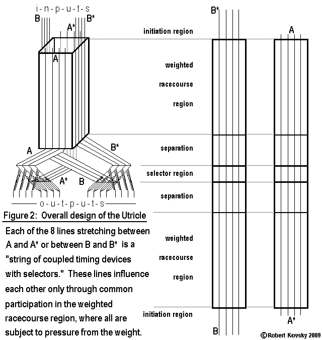
|
|
The adjacent Figure shows a racecourse incorporated into a model for a "utricle," that is, a device that detects tilting with respect to the force of gravity. A weight hangs within the central channel. If the device tilts, the weight rests on pressure-sensitive timing devices. The responding period δ in a pressure-sensitive device is lengthened in proportion to the effective weight. Hence, pulse waves are slowed down in a side where the weight rests on timing devices. Selectors are device attachments like those in the preceeding string device that detect pulses traveling in one direction but not in the other.
|
Shimmering Sensitivity
The images below show the process of Shimmering Sensitivity in a Quad Net Field. The process embodies the contest principle.
The process starts with a blank Quad Net Field, shown in Figure 1. The Field is made up of interacting elemental devices. Each elemental device in the Field is set to act like a two-pulse timing device. That is, if two pulses arrive through two different projections at nearly the same time, the timing device will be triggered and will then respond. A single pulse will not trigger the device.
Figure 2 shows a set of waves that the Field can support, each wave having its own direction. Waves can have a variable number of elements in a cycle. In Figure 2, there are four elemental devices in each cycle. When elemental devices are set to operate like two-pulse timing devices, only these kinds of waves can be supported.
1. Primal Quadnet Field
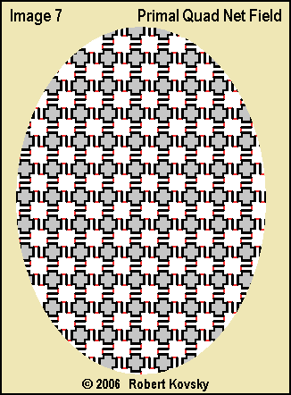
|
2. Four possible waves

|
3. Shimmering fragments of waves
|
4. The winning wave
|
Figure 3 shows a Critical Moment in a Quad Net device part. The device part has thousands of elemental devices that are repeatedly discharging. Timing intervals δ and β vary with respect to each other. During a cycle, δ > β changes to β > δ. Activity when δ > β is like signal generators. When one set of devices discharge they trigger a second set of nearest neighbors that, in turn, trigger the original set. The activity is alternating checkerboard patterns. Activity when β > δ is in the form of waves. As the change occurs, at the instant δ = β, germinal activity patterns of multiple possible waves appear in the device part. Then, as the cycle proceeds and the Critical Moment resolves, a single wave occupies the entire Field, as shown in Figure 4.
The principle of the contest is embodied in the operations of the Quad Net device part where changing timing intervals produce a Critical Moment. At the first instant when
β first becomes greater than δ, multiple possible patterns are generated in a germinal form and each could conceivably dominate and exclude the others. As the cycle proceeds, through the course of action, the multiple possible patterns are transformed into a single actual pattern, which occupies the Field until silenced by cyclical activity, so that the Field can be readied for a new contest. as shown in Figure 4..
Such device activities embody the principles that also generate a person's experience, I suggest, when choosing among menu items in a restaurant. First one possible selection is mentally tasted, then another, and the possibilities compete in the mind. However, the serving person is "ready and waiting" and the Critical Moment resolves, as such Critical Moments do, with one actual meal order out of all meal orders possible at that restaurant. During the Critical Moment, the possibilities are in a contest in the mind of the person. The contest principle thus stands as a principle of consciousness and freedom.
( ... ) top of page
8. Link List
"Brain Models Built From Timing Devices"
( ... ) Opening Page
( ... ) A Kit of Parts
( ... ) An Eye for Sharp Contrast
( ... ) Eyes That Look at Objects
( ... ) An Ear for Pythagorean Harmonics
( ... ) A Procrustean Group of Harmonies
( ... ) Fundamentals of Timing Devices
( ... ) Author & History
Related Materials
( ... ) Quad Nets
( ... ) Testimony of Freedom (current long-range project)
( ... ) Embodiment of Freedom (archives of development)
Your comments and suggestions are welcome.
Please write to the adjacent email address (shown in an image to minimize spam).
|

|
3/14/11
Copyright © 2011 Robert Kovsky


