Timing device assemblies embody a principle of action. The action content of timing device systems is expressed in streams of pulses. A pulse resembles a "spike" or "action potential" in biological brains. Each pulse is an instantaneous package of action. A stream of pulses measures an environmental influence or bodily condition such as light or pressure; and bundles of pulses activate muscles.
Timing devices process pulses and streams of pulses. An operational unit built from timing devices – a module – generates or processes a stream of pulses in ways that may be simple or complex. Modules can act in two or more ways and a system built from modules can have a great many ways of acting that are organized into a repertoire. In a suitable environment, a system can start ways of acting, stop ways of acting, maintain ways of acting, speed up or slow down a way of acting, select from among multiple ways of acting, switch between multiple ways of acting and/or combine multiple ways of acting. Long-range goals involve designs where multiple streams of action are maintained simultaneously, along with with speed changes, selections, switchings and combinations. Streams of action are to be interwoven like musical themes or hybridized strains of plants. Ongoing speed changes, selections, switchings and combinations may keep a system in operation within challenging environments or lead to new forms of action.
The presentation on this page shows essential elements of the timing devices system as simply and compactly as possible. The timing devices system is a kit of parts, resembling a set of electronic circuit components that contains resistors, capacitors, power supplies, transistors, etc. The presentation shows how parts from the kit of timing devices can be used to build systems that lead to operational models of parts of working brains, with a developmental sequence involving signal generators as a chief example. ( ... ) "An Ear for Pythagorean Harmonics" (2009) and ( ... ) "An Eye for Sharp Contrast" (2011) are built from the kit of parts presented on this page.
2. Timing Device Signals
Timing device constructions begin with signals that have exact, perfectly defined forms called ideal. The class of ideal constructions includes Euclid's geometry, the Ideal Gas Law (pV=nRT) and Maxwell's Equations. Operations with ideal signals are the first and easiest goals of design projects. A system that operates with ideal signals is tested with other signals, identifying shortcomings and failures when compared to operations with ideal signals. As shown in practice in these pages, identification of shortcomings and failures can suggest improvements and lead to development.
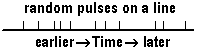
| A timing device signal is made up of a sequence of pulses. All pulses have the same form: a distinct and identifiable package of action that exists for only a specific instant in time. Pulses appear on lines or "projections" between timing devices and they travel instantaneously between timing devices. That is, during its instantaneous existence, a typical pulse is produced or discharged by one timing device, travels through a projection and arrives at a second device. The adjacent Figure shows "random" pulses and the distinct times they appear on a particular line. |
|
A time interval between consecutive pulses on a line, called a period, is an exact real number, defined as the time difference between the two instants of appearance. Generally, any units of time may be chosen for the purposes at hand, e.g., hours, minutes, seconds, milliseconds, microseconds. Designs in these pages contemplate time units of seconds or milliseconds (similar to brains) but without actual specification, leaving possibilities open.
[In the Quad Net Model, a pulse is a package of "virtual energy." Virtual energy is the fuel for device operations, conceptually based in a source that resembles glucose distributed to brain parts through blood flow. In simplified models, e.g., timing devices, all units are fueled by "steady state" inflows of such fuel. Virtual energy is stored in devices and some virtual energy is converted into pulses. Virtual energy is mostly dissipated (not conserved) rather than converted into pulses. In the Quad Nets model, virtual energy is transferred between devices in pulse packages with shapes, sizes and durations that can be systematically varied. The pulse package for timing devices is an idealized limit point of the variations, resembling a dirac delta or heaviside function. Timing device systems are thus a particular, limited version of the Quad Net Model of brains. See ( ... ) Quad Nets, § 4.]
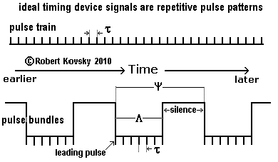
The Figure below shows two ideal timing device signals: a pulse train and pulse bundles.
|
An ideal pulse train is a perfectly repetitive sequence of pulses with exactly the same time period, τ, between any two pulses.
Ideal pulse bundles are specified by three fixed time periods: τ, Λ and ψ. Within an ideal bundle, the "signal period" between any two pulses is τ. Each bundle lasts for a "durational period," Λ, that extends from the first pulse in a bundle, called the "leading pulse," until the last pulse in the bundle. Λ plus a period of silence make up the period ψ between bundles, called the "organizational period," which is measured by reference to time between succesive leading pulses. In an ideal signal, Λ/τ is an integer and the number of pulses in the bundle, n = (Λ/ τ) + 1. For fixed ψ, leading pulses are invariant even if n, τ and Λ are varying. |
As shown below in the ( ... ) model of muscle activation, timing device systems use pulse bundles to trigger and control muscle-like action. Each bundle causes one twitch of a muscle fiber. Many muscle fibers run between points of attachment on bones and make up a muscle. A steady muscular force can be maintained if fibers are stimulated by waves of pulse bundles cycling through the fibers. The signal period, τ, sets the force of a twitch, a smaller τ resulting in a higher force.
( ... ) top of page
3. The Primal Timing Device
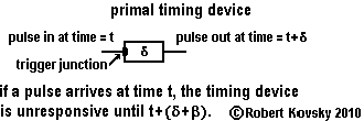
| The primal timing device, shown in the adjacent Figure, is the point of origin for timing devices. A pulse arrives through the trigger junction of the primal timing device and the device responds by discharging a pulse after a time period δ, called the responding period. The timing device is not responsive to another arriving pulse during the responding period. After discharging, the primal timing device continues to be non-responsive for an additional time period, β, called the refractory period. |
|
After both the responding period and the refractory period have expired, the device again becomes ready to respond. The course of activity from the arrival of the triggering pulse through to return to responsiveness is called the response process. While the response process is running, the device is unresponsive. During the response process, the device discharges an output pulse. The discharge occurs after the arrival of the input pulse, with a wait time of δ; and the discharge occurs before the device returns to responsiveness, with a wait time of β.
The responding period δ and the refractory period β are timing intervals, quantities that define the primal timing device, like the number of ohms defines a resistance.
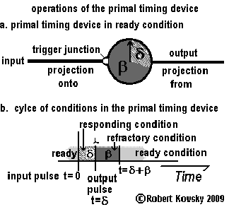
The Figure below shows operations of the primal timing device along with some additional terminology. In Figure a, the body of the device resembles a stop watch used in sports contests. The arrival of an input pulse "pushes" the trigger junction and starts the pointer on its one-revolution cycle. Figure b shows the cycle of conditions that occur during the response process.
|
Figure a shows the projection onto that carries input pulses to the device through the trigger junction and the projection from that carries output pulses discharged by the device. A projection from one timing device becomes a projection onto another timing device, as shown in the signal generators in the next section.
As shown in Figure b, the primal timing device has three conditions and operations cycle through the conditions. The device starts in the ready condition. When an input pulse arrives through the projection onto and activates the trigger junction, the device enters into the responding condition, which continues for the responding period δ. At this point, the device discharges a pulse through the projection from and enters into the refractory condition, which continues for the refractory period β. Then, the device re-enters the ready condition, completing the response process. The primal timing device responds to an input pulse only when it is in the ready condition. |
( ... ) top of page
4. Signal Generators Built From Primal Timing Devices
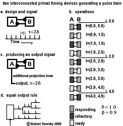
The Figure below shows two interconnected primal timing devices that work together to generate a signal. Figure a shows the reciprocating arrangement of the devices. The signal on each projection is a pulse train with period τ = 2δ.
|
Figure b is a time chart of operations of the signal generator. Activity in each device is governed by the timing intervals δ = 1.0 and β = 0.9. Any base unit is permissible, e.g., microseconds, seconds, minutes — here, it is convenient to think in terms of seconds.
At time t=0.0, device B discharges a pulse which immediately arrives at the trigger junction of device A and causes it to start responding. Between time t=0.0 and t=0.9, device B is in the refractory condition and device A is in the responding condition. At time t=0.9, the condition of device B changes to the ready condition. Betwen t=0.9 and t=1.0, device A is still responding and device B is ready. At time t=1.0, device A discharges a pulse and its condition changes to the refractory condition; the pulse discharged from device A immediately arrives at ready device B and changes its condition to the responding condition. At time t=1.9, device A becomes ready. At time t=2.0, device B discharges a pulse and becomes refractory; and the pulse causes device A to enter into the responding condition. An operating cycle has been completed, which repeats. In Figure c, a second projection from is added to timing device A. This carries the same signal as shown in Figure a. That is, both projections from timing device A carry identical signals. When there are multiple projections from a timing device or ramified (branched) projections from a timing device, each projection from and each ramification carries "the same" signal. This is called "the equal-output rule." The principle is depicted in Figure d. |
|
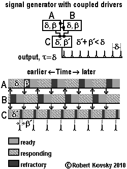
The design for a "signal generator with coupled drivers" is shown in the Figure below. The design starts from the signal generator just shown (timing devices A and B) and adds a third timing device, "C." Responses in C are triggered by pulses from both A and B. The output signal of C, τ = δ, has a rate that is double that of the prior design.
Timing device C has a responding period, denoted by δ', that is different from that of timing devices A and B, denoted by δ. Similarly, β' is different from β. C must complete a whole cycle in less time than δ, the time it takes for A or B to discharge after being triggered. In other words, proper performance requires operations that comply with the constraint δ' + β' < δ.
|
The pulse patterns in strips in the adjacent Figure illustrate how conditions in the three devices cycle with respect to each other during operations. In this example, β is equal to (4/9)δ. Patterns in devices A and B show that cycles of conditions are "the same" in those two devices except for a time displacement. Discharges between devices A and B are shown as arrows between the two individual strips. As shown by arrows directed at C, each discharge of A or B also triggers C, which is pulsing twice as fast as A or B.
Because of uniform cycling, it is possible to define a "readiness period," denoted by γ. In A or B, δ = β + γ. This means, as shown in the strips, that during the time that one device is responding, the other device goes through the refractory period and waits in the readiness condition until it is triggered. Then, γ = δ – β. In C, γ' = δ – (δ' + β'). This is because device C is triggered cyclically with a period of δ. After going through the responding period (δ') and the refractory period (β'), C awaits the next pulse and the amount of waiting time is called the readiness period. The C strip shows that δ = δ' + β' + γ'. |
Suppose that we slowly increase the timing intervals of C (δ' and/or β') until they violate the constraint δ' + β' < δ. During this process, γ' shrinks to 0 and then the system fails to maintain operations. Suppose that the constraint is violated, but only by a small amount. A and B are still generating pulse trains, only C is not able to handle all the pulses. Operating in violation of the constraint, C does not complete a cycle after a first trigger pulse before the second trigger pulse arrives; so C does not respond to the second pulse. C is, however, ready when the third trigger pulse arrives. Operations after the third pulse are the same as after the first pulse. Hence, if the constraint is violated, but not by too much, the system generates output pulses at half the frequency compared to when it is operating in an ideal fashion.
( ... ) top of page
5. Gate Devices
Electrical and electronic gate devices include electrical relays, vacuum tube triodes and junction point transistors. The gate principle is also embodied in gate timing devices, simply called gate devices within the timing devices systems. In all gate devices, regardless of technology, the passage of a stream of activity from input to output is subject to signals arriving over a third line. Signals arriving over the third line are controlling signals, often referred to as modulation.The Figure below illustrates the principle of the gate device in timing device systems. The gate device has two kinds of operations. In the first kind of operation, it acts exactly like the primal timing device: the device "passes" pulses with a delay, δ. In the second kind of operation, it is unresponsive to input and produces no output. The first kind of operation is called "the gate is open" and the second kind of operation is called "the gate is closed." Modulation pulses through the third line arrive at the modulation junction and control switching between the two kinds of operations, opening or closing the gate.
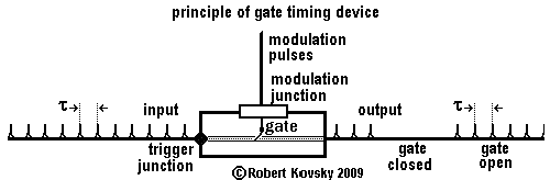
There are two kinds of gate timing devices:
• gate normally-closed devices —a modulation pulse opens the gate, changing an unresponsive device into a primal timing device for a specific amount of time.
• gate normally-open devices —a modulation pulse closes the gate, changing a primal timing device into an unresponsive device for a specific amount of time.
( ... ) top of page
5a. Gate Normally-Closed Device
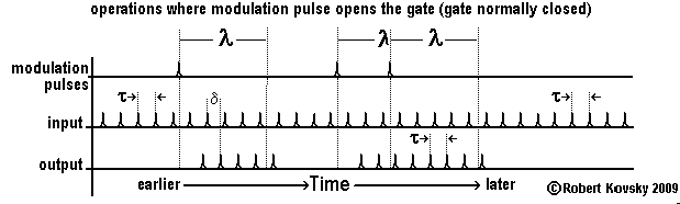
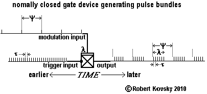
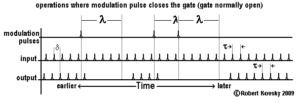
The Figure below shows operations of the gate normally-closed device. Input pulses are arriving continually but the device responds to them only after the arrival of a modulation pulse and then only for a period λ, called the modulation period. A modulation pulse opens the gate that is normally-closed.
If a fresh modulation pulse arrives before the expiration of the modulation period following a prior modulation pulse, the gate remains or stays open for an extended period, namely, for a full modulation period that starts from the arrival of the fresh pulse, as shown in the Figure. If pulses in a pulse train are arriving through the modulation line more quickly than once every λ, the gate stays open and the device acts the same as a primal timing device.
|
The adjacent Figure shows the box-like symbol for the gate normally-closed device and an application as a generator of pulse bundles. The symbol shows modulation input arriving at the device through a "layer" in contrast to the point-like junction for the trigger input.
In general, device operations of the pulse bundle generator in the adjacent Figure are not quite ideal even if both the signal period τ and the organizational period ψ are perfectly ideal. If ratios ψ/τ and λ/τ are numbers other than integers, there will be "wobbles" in the timing and sizes of bundles, as shown in the adjacent Figure (where the ratios are fractions). A different design for a pulse bundle generator does not have a wobbly output; see the ( ... ) "streaming device," discussed in § 10 below. |
( ... ) top of page
5b. Gate Normally-Open Device
The Figure below shows the gate normally-open device, which operates like the primal timing device except for a period λ after the arrival of a modulation pulse, during which it is unresponsive. A modulation pulse closes the gate that is normally-open.The arrival of a second modulation pulse while the gate is closed following a first such pulse extends the closure of the gate for the period λ after the arrival of the second pulse. If pulses arrive faster than once every λ, the gate stays closed.
Comparing the Figure for the gate normally-open device with that for the gate normally-closed device shows an "opposite pattern" resemblance, recalling that between a photographic negative and print. The resemblance occurs through the passage of time rather than by comparing fixed objects. The comparison is like comparing tunes rather than triangles.
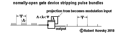
| The adjacent image shows the box-like symbol for the gate normally-open device and its operations as a "bundle stripper" that passes the leading pulse in pulse bundles but none of the later pulses. The leading input pulse in a bundle triggers the discharge of an output pulse but that first output pulse closes the gate to later pulses in the bundle. The period of closure, λ, is chosen to support proper operations of the "bundle stripper." So that the gate is closed for the entire bundle, it is sufficient that λ > Λ. So that the gate is open when the leading pulse in the next bundle arrives, λ < ψ. Hence the constraint on operations is Λ < λ < ψ. |
( ... ) top of page
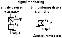
5c. Signal Monitoring Device
The function of signal monitoring is shown in the Figure below in two ways, (1) through an assembly of two gate devices and (2) through a novel unitary device, called a signal monitoring device. In either approach, a short-period τ signal may or may not be present on the incoming trigger input line. Cyclically, with a long ψ period, a pulse is sent over a modulation line. If the short-period signal is present when the ψ pulse arrives, the monitor discharges a single output pulse; but no output pulse is discharged if the short-period signal is absent. The short-period τ signal is being monitored.For fastest opertions, τ is just a bit longer than the sum of the primal timing units, δ + β of the timing devices used in the signal monitoring device. Operations are generally keyed to ψ~nτ where 10 < n < 100.
Signal monitoring devices are used in ( ... ) "An Eye for Sharp Contrast."
|
In Figure a, the monitoring function is performed by two gate devices, one each of the normally-closed and normally-open kind, each operating as shown in the previous examples 5a and 5b. The ψ pulse opens the gate of the gate normally-closed device and generates a pulse bundle with a signal period τ. There may be only a single pulse in the bundle or there may be many. The leading pulse in the pulse bundle, after triggering the gate normally-open device and immediately upon discharge by it, closes the gate of that device for a period of λ2, which will perform its desired function of limiting the output to a single pulse if λ2 > λ1. If the τ signal is present, the monitor in Figure a will discharge an output pulse at a time that is between 2δ and (2δ+τ) after the arrrival of the ψ pulse.
The new signal monitoring device shown in Figure b improves on the speed performance of the design in Figure a. The new device has its own set of rules. The rules start with those for the normally-closed gate device and then additional rules are incorporated. Additional rules involve the additional junction, called a secondary modulation junction. The secondary modulation junction is responsive only while the primary modulation junction is activated by the recent prior arrival at it of a modulation pulse. The added function is an immediate response to a pulse through the secondary modulation junction that "closes the gate" and makes the device unresponsive for the remainder of λ1. If the τ signal is present, the monitor in Figure b will discharge an output pulse at a time that is between δ and (δ+τ) after the arrrival of the ψ pulse. Speed of output production after input is improved by one δ, about 30% over the assembly shown in Figure a. |
( ... ) top of page
5d. Signal Generator Controlled by Input Signal
|
The adjacent Figure shows development from previous designs to construct a "signal generator controlled by input signal." The output signal, τo , is a fixed ideal pulse train with τo = δ as in the ( ... ) "signal generator with coupled drivers" shown above in § 4. The three devices A, B and C are reproduced in the new design except that timing device B, originally a primal timing device, has been changed into a gate normally-closed device. A fourth timing device has been added to the assembly, the gate normally-open device (D).
Functioning of the signal generator depends on the input control signal. As long as pulses in the input control signal, τi , arrive at the gate normally-closed device (B) faster than once every λ1, the gate will be kept in an open condition. That is, if the input signal has τi < λ1, the signal generator will continue to produce an ideal pulse train. If the control signal becomes silent, however, the gate normally-closed device B becomes unresponsive to a pulse from timing device A and the signal generator ceases pulse production, falling silent. Problematic operations when τi > λ1, especially when τi ~ λ1, are resolved in the next section. Suppose both the input signal and the signal generator are silent and then an input signal appears, with pulses arriving faster than once per λ1. This opens the gate in device B and makes it ready. To get the signal generator started, the newly-active control signal triggers the gate normally-open device labeled "D" and the pulse that device D discharges then triggers device A in the signal generator. Device D is like the starter on an automobile engine that "kicks" it into operation. Almost immediately, device A starts discharging pulses that keep the gate in device D closed until the generator falls silent again; this prevents the input control signal from causing discharges into the signal generator during ongoing operations, which would roughen the output stream. Normal operations require uninterrupted gate closure of D; hence, the modulation period of the gate normally-open device, λ2 must be greater than 2δ, a simple constraint to satisfy.
|
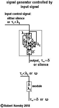
|
A gray box is drawn around the device assembly to show that the "signal generator with start/stop control" has the nature of a distinct device; indeed, that it resembles a unitary timing device like the gate devices or the signal monitoring device. Such a unitary assembly is called a module. More generally, a module is a unitary assembly of timing devices that can be used along with individual timing devices in a common way in larger device designs.
The module in the Figure above operates according to the rules that "input τi < λ1 produces output τo = δ" and "silent input produces silent output." That is, specific input signals produce specific output signals. The symbol ω is introduced to stand for silence.
( ... ) top of page
6. Two-Pulse Device
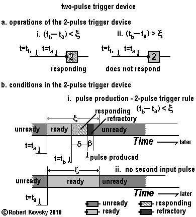
|
The adjacent Figure shows operations and conditions for the two-pulse device. Two trigger input pulses are needed to start the response process and the second pulse must arrive no later than ξ after the first. If a second pulse arrives too late, the device does not respond. ξ is a timing interval like δ and β and is called the readiness period.
If an ideal pulse train with period τ is the input pulsestream, where The changing conditions of the two-pulse device shown in Figure b can be compared with those of the primal timing device. Recall that the conditions in the primal timing device are "ready," "responding" and "refractory." A new condition has been added to the two-pulse device, the "unready" condition. In the two-pulse device, the unready condition is the stable or default condition. An initial trigger input pulse changes the unready condition to the ready condition. The ready condition lasts no longer than the readiness period ξ. (i) If a second pulse arrives within ξ, the ready device changes to the responding condition and then acts exactly like the primal timing device. (ii) If no second input pulse arrives until ξ elapses, the device returns to the unready condition without responding. Another initial input trigger pulse is required to make it ready again.
|
|
In the adjacent Figure, a two-pulse device is combined with the module "signal generator controlled by input signal" described in the previous section to construct the "signal generator with start/stop control," the culminating design in this series.
Suppose that the input signal, τi, is a slowly variable pulse train with a pulse period that is sometimes larger than ξ and sometimes smaller. The two-pulse discharges output pulses when τi < ξ but not when τi > ξ. The two-pulse device thus acts like a "high-pass" filter in an electronics circuit; the output reproduces an input pulse stream (but at half the frequency) if the input stream has a period smaller than ξ but is silent otherwise. The two-pulse device thus "filters out" signals that fall into the problem area of the "signal generator controlled by input signal" noted in the previous section, as long as signals change slowly. |
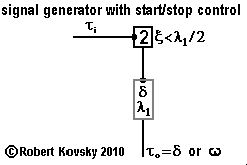
|
The readiness period of the two-pulse device, ξ, is set at λ1/2. An input signal τi with pulses arriving faster than once per λ1/2 will result in output pulses from the two-pulse that start the signal generator and keep it going. When the arriving pulse rate slows below once per λ1/2, output from the two-pulse device ceases and the signal generator shuts down.
Two signal generators with start/stop control, with output periods τ and ψ respectively, are used in ( ... ) An Eye for Sharp Contrast.
( ... ) top of page
7. Difference Device
|
The difference device shown in the adjacent Figure performs "frequency subtraction."
If input signals are two ideal pulse trains with frequencies fμ= ( 1/τμ ) and fν= ( 1/τν ),
where fμ > fν (or, equivalently, τν > τμ ), the output signal will have a frequency of fρ= fμ – fν.
|

|
A pulse train that is only approximately ideal may have a "frequency" that is functional even if not perfectly defined. Call if "sufficiently defined." The difference device embodies a principle of exact subtraction that is most closely realized when inputs are ideal pulse trains. When signals deviate from ideal pulse trains, exact operations may be maintained for "sufficiently defined signals." One example is a pulse train with a period that has only slow variations, e.g., a change of period of no more than 1% between successive periods. Continuous pure musical tones generate ideal pulse trains, which are explored in ( ... ) "An Ear for Pythagorean Harmonics."
Difference device operations with other input signals may follow the subtraction principle only approximately and some signals cannot be brought within the subtraction principle as presently embodied in the difference device. For example, exact operations with pulse bundles are possible but they require tight coordination. The subtraction principle fails if an entire subtrahend input bundle arrives during the silent part of the trigger input signal.
Some details of operations of the difference device are shown in the Figure below. Trigger input pulses arrive in an ideal pulse train denoted by "μ," as shown in Figure a, where the period between pulses is 5δo.
An ideal pulse stream, denoted by "ν," arrives through the subtrahend input. During operations, each subtrahend pulse "cancels" the next trigger input pulse, reducing the output flow by one pulse. Exact operations require that subtrahend pulses arrive less frequently than trigger input pulses, e.g., with the period of 7δo shown in Figure b.
In Figure b, input pulses are shown with marks at the top of each pulse stroke, "x" for trigger input pulses and "0" for subtrahend input pulses. Pulses in the output pulse stream – ρ – are triggered at instants marked with an "*." An output pulse is triggered by any trigger input pulse that has not been canceled by the prior arrival of a subtrahend pulse.
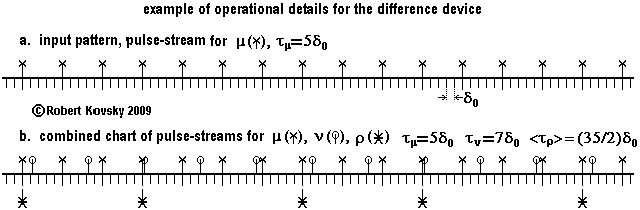
As illustrated in the Figure, the output signal will generally not be ideal but only an approximation to an ideal signal. The period between successive output pulses is either nτμ or (n+1)τμ. In the Figure, periods between output pulses are either 15δ0 or 20δ0 . Equivalently, such periods are either 3τμ or 4τμ. A mix of these two periods produces the average output period, which lies in between. In general, if there are two ideal input pulse trains, the difference device produces an output signal that is made up of a mix of two periods with a size difference of 1τμ.
That is, the output signal from a difference device generally has a "wobble" of size 1τμ. The timing of the wobble in output generated from two ideal input pulse trains is repetitive but, in general, it has its own wobble. A wobbly output is inherent in the present design of the difference device.
An output signal from one difference device can be used as an input to another difference device. For example, when difference devices feed one another in a ladder with steps – as in ( ... ) An Ear for Pythagorean Harmonics – the wobble's timing rapidly becomes more complicated as levels increase. Fortunately, the timing of a wobble does not appear to cause errors in generating an exact difference. What might cause errors is an increasing size in the wobble, i.e., if it were to grow progressively larger relative to the average period between pulses. In the Ear for Pythagorean Harmonics, where original inputs are ideal pulse trains (pure tones) and where f and g and their relations are within the constraint g < f < 2g, investgation has uncovered no effect from wobbles. Rather, it appears that wobbles grow slowly, if at all, and that downstream operations overwhelm possible effects from wobbles. In the event of problems, the relative size of wobbles could be reduced by passing output through a ( ... ) "streaming device," discussed in § 9 below.
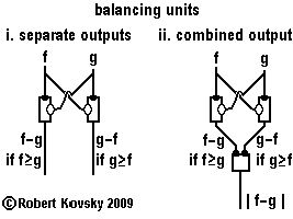
|
The adjacent Figure shows an important use of difference devices, in two versions of "balancing units." In each version, two difference devices are hooked up to two pulse streams (f and g) that serve as input and subtrahend, in mirrored pairs. If two defined pulse streams arrive through f and g with different frequencies, one difference device in a balancing unit will be producing output in the form of a "difference signal;" the other difference device will be silent. If the two pulse streams are identical (or nearly so), both lines will be silent.
Figure i shows a balancing unit with separate outputs.
In the balancing unit shown in Figure ii, the outputs from the two difference devices are inputs to a simple timing device. At any moment during controlled operations, no more than one difference device generates input to the simple timing device and the simple timing device responds like a primal timing device. The possibilities are combined in the formulation |
( ... ) top of page
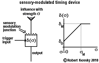
8. Sensory-Modulated Timing Device
| The adjacent Figure shows a sensory-modulated timing device. The responding period, δ, measures an influence based in the external environment or in the body of an animal, e.g., light, external pressure or internal blood sugar level. The influence acts through an input to the sensory modulation junction and the length of the responding period δ is a function of the strength of the influence, denoted by σ. When a trigger input pulse arrives, the responding period δ of the device is fixed for that particular responding process at its momentary value as modulated by the influence.
It is convenient to use the linear response function shown in the adjacent Figure; if the influence varies between σ = 0 and σ > σM, the responding period varies between δ0 and δM. That is, when there is no influence, the responding period is at its minimum, δ0. As the influence increases in intensity, the responding period becomes longer until it reaches its maximum, δM. For example, δM = 5δ0 in ( ... ) An Eye for Sharp Contrast. |
|
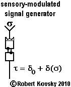
| The adjacent Figure shows a signal generator where one of the timing devices is a sensory-modulated timing device. The output signal has a variable period, τ = δ0 + δ(σ). If δM = 5δ0, the output frequency will range from f = 1/τ0 to f = 1/(3τ0), where τ0 = 2δ0. For example, the output frequency can vary between 60 and 20 Hz and the varying frequency measures the varying strength of the sensory influence. |
|
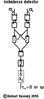
|
The adjacent Figure shows an "imbalance detector." Two sensors face in opposite directions and each measures the strength of an environmental influence. If the two strengths are approximately the same, the output of the "signal generator controlled by input signal," (...) § 5d above, is silent. If the difference between the two strengths reaches a certain point, the signal generator turns on and produces the output signal with a fixed period, τ0.
The two sensory-modulated signal generators drive a balancing unit with combined output, described above in § 7. The left generator is subject to environmental influence σl. The right generator is subject to environmental influence σr – with subscripts "l" and "r" standing for "left" and "right." The sensory devices are pointed in different directions and the strengths of the environmental influences will sometimes be different for the two sensory devices, leading to different frequencies in the output signals of the two sensory-modulated signal generators. When signals with different frequencies drive the balancing unit, the frequency of the output signal from the balancing unit is a measure of the "imbalance" between the two sensory influences. The combined output has a frequency close to As discussed previously, when the input signal to the two-pulse device has a sufficiently high frequency, the signal generator module will turn on. Otherwise, output from the signal generator module is silent. Overall operations are such that the signal generator module turns on if the imbalance is above a specific level and turns off if the imbalance falls below that level. The system performs the function of detecting and signaling an imbalance. |
The imbalance detector is the germinal element for the "Differentiation Layer" in the Edge Detector, a module in the ( ... ) Eye for Sharp Contrast. The Edge Detector detects an imbalance between outputs of nearest-neighbor photo-sensitive devices when an edge in an optical image darkens one photo-sensitive device much more than a neighboring photo-sensitive device.
( ... ) top of page
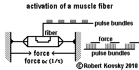
9. Model of Muscle
In timing device models, a physical muscle is made up of a set of muscle fibers. All the muscle fibers in a muscle connect two points of attachment, e.g., on bones, in a nearly-identical way. When a pulse bundle arrives at an individual muscle fiber, the muscle fiber twitches forcefully. A muscle fiber rests between twitches. A sustained muscular force is caused by cyclical twitchings of muscle fibers in a muscle that are driven by waves and cycles of pulse bundles.Serious development must await actual devices. Suggested ideal devices are shown in the Figures below.
|
The adjacent Figure shows a proposed muscle fiber and its activation. For purposes of presentation, the fiber is shown with two extended "strings" that are attached to two immoveable "walls." The fiber is stimulated by ideal pulse bundles arriving cyclically, including periods of silence. In cycles of equal duration, the muscle fiber twitches and relaxes. Each twitch exerts a constant force F while it is occurring. In this model, F varies directly (or linearly) as the frequency f, where f = (1/τ).
The timing of F is defined independently. In this model, a twitch starts only when there are at least three pulses and it starts half a period after the arrival of the third pulse. The duration of the force is equal to the durational period of the bundle plus one pulse period τ.
|
|
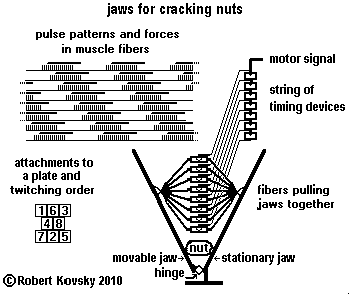
| The adjacent Figure shows a part of the motor system of "jaws for cracking nuts." The force applied by the jaws to a nut is controlled through pulse bundles in a motor signal that is distributed to muscle fibers, which twitch in response.
Each of the fibers in the jaws system acts like the fiber in the previous Figure, alternately twitching and relaxing. The string of timing devices distributes the motor signal so that the twitchings are spread out in time. As a result, the sum of the forces on the jaws is approximately constant. Because physical objects exclude one another spatially, attachments of fibers cannot be identical. However, the problems can be minimized as shown in the Figure by a spatial arrangement or "plate" of attachments. The Figure also shows the order of twitchings. A cycle of twitchings moves the forces around on the plate but in a way that sums up close to constancy. The overall design is suggestive of further projects, e.g., "a fishtail for propulsion." Jaws and fishtails couple to external materials (nuts and water) that make idealized designs difficult. An easier development path is pursued in Eyes That Look at Objects |
10. Memory Devices
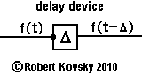
Unanswered questions about memory point to important areas for future development of timing device systems. In contrast to computers – where memory is part of the original design – memory units in timing device systems come in at later stages.One potential path of development begins with the primal timing device. In the primal timing device, the responding period δ is fixed and fundamental in the sense that other timing intervals are defined in terms of δ. In some designs, δ constitutes a fundamental unit δ0.
| Some simple memory devices extend or accumulate responding periods. The delay device shown in the adjacent Figure takes the fixed timing interval δ and turns it into a variable Δ that can take on a range of values, say from Δ=1δ0 to Δ=50δ0. The delay device delays each pulse by Δ. Supposing the device to have a refractory period β, input trigger pulses must be separated by a period of at least Δ + β for each input pulse to produce an output pulse. Three devices of this design are used in An Eye for Sharp Contrast where they coordinate activities of device parts that operate with a common cycling period. |
|
|
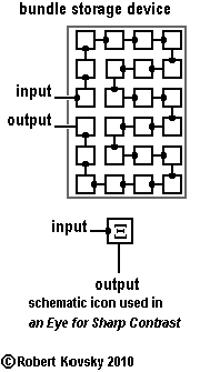
The bundle storage device shown in the adjacent Figure can temporarily store pulse bundles. Suppose individual devices in the bundle storage device share a common responding period δ and a common refractory period β. The total storage, denoted by Ξ, is for a specific amount of time: Ξ = 24δ.
Two bundle storage devices can be connected to each other in a way that resembles the arrangement of primal timing devices in the ( ... ) original signal generator. One storage device rests while the other storage device processes the pulse bundle. Once a cycle, one device switches from passive to active and the other switches from active to passive. At the opposite end of the cycle, the devices switch back. "Passive" in a bundle storage device resembles "refractory or ready" in a primal timing device; and "active" resembles "responding." A bundle storage device of this design is used in the Eye for Sharp Contrast, denoted by the iconic symbol in the adjacent Figure. |
Streaming devices
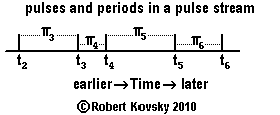
| Another potential path of development is based on streaming devices. This path begins with development of the concept of the pulse stream. Pulses in the adjacent Figure have occurred at particular instantaneous moments in time, namely, t2, t3, t4, t5 and t6. Periods, denoted with "π," are derived quantities that require knowledge of pulse moments and that follow the form: πn = tn – tn–1, e.g., π5 = t5 – t4. Instantaneous pulse moments have no necessary relations among themselves other than a minimum spacing; but periods can relate to one another to make up a signal. E.g., ideal pulse bundles defined by periods τ, Λ and ψ. |
|
The Figure below shows a simple streaming device used as a generator of ideal pulse bundles. The device has a 1-unit memory where it stores the size of the most recent period in the input signal, πφ. When a new input period is received, the size of the newer period replaces that of the older one in the memory. The momentary period in memory sets the next period between output pulses. Timing of pulses in an output bundle reproduces timing of pulses in the π input pulse stream. If the input pulse stream is an ideal pulse train, the output will be ideal pulse bundles for any πφ, ψ and λ within nested ranges of values. The fixed λ sets the durational period of pulse bundles.
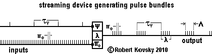
| As to operational details, the arrival of a pulse on the ψ line triggers the primal response process in the device that causes the discharge of the leading pulse in an output bundle after the expiration of the responding period δ. The clock that tracks the timing interval λ starts on the discharge of the leading pulse in the output bundle, in contrast to ( ... ) gate devices, where the λ clock starts on the arrival of a modulation pulse. When λ expires, the device stops discharging pulses but continues to replace πφ in memory. It awaits the arrival of the next pulse on the ψ line to start discharging again. |
During discharge operations, as it starts a response process, the streaming device sets the time when it will start the next response process. Thus, at the onset of a pulse bundle, immediately on arrival of the ψ trigger pulse, as the first response process commences, the streaming device sets the time that it will start the second response process. The period or time inverval between the first and second response processes is equal to that stored in the 1-unit memory, namely, πφ. When the the device starts the second response process, it sets the time when it will start the third response process, using the time interval πφ then in memory. Such cyclic activity continues until the device ceases to discharge pulses upon the expiration of λ.
The operations of the streaming device generate pulse bundles, with the signal period, πφ, taken from the input pulse stream and the organizational period, τ ψ, arriving as an input. The "operational period," λ, is set as a specification of the streaming device. The durational period of the pulse bundle that is produced, Λ, is less than λ but the difference between λ and Λ is less than one pulse period.
If the input periods, τψ and πφ are ideal pulse trains, the output bundles will be exact copies of one another in both size and timing. Output from this device does not include the wobbles that are produced by the ( ... ) gate normally-closed device operating as a pulse bundle generator.
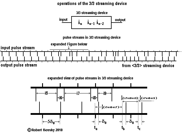
The Figure below shows the operations of a more advanced streaming device, a 3/3 streaming device. Operations of the 3/3 streaming device resemble those of the previous streaming device, with (1) primal activation of the leading pulse and (2) cyclical scheduling of the next pulse according to the contents of memory. In contrast, however, there is no timing interval λ; rather, the 3/3 streaming device runs on a continuous basis. More significantly, the 3/3 streaming device calculates the period between two output pulses as the average of the past three periods between the last four input pulses. That is, the memory stores the sizes of the three most recent periods in a "register," (borrowing a term from compuer technology) as shown in the Figure, using the notation in, in–1 and in–2 for such sizes. Storage is by the method of "first in, first out." When a newer period, in+1, appears, its size goes into the register, replacinig the oldest period on the left; in–2 is deleted; and the other two periods each shift one place up in the register. This design combines pulsational and computational or algorithmic methods.
Thus, the 3/3 streaming device sets the time interval between output pulses equal to the average of the three most recent input periods. The period between output pulses is a "3-period moving average" of recent input pulse periods. The construction resembles that of a "30-day moving average" in stock market share prices.
As shown in the Figure, the result of operations of the 3/3 streaming device is that the average output frequency is approximately equal to the average input frequency and that variations have been smoothed. For example, the 1τμ wobble noted in output of the ( ... ) difference device operating with ideal pulse train inputs would be spread-out, e.g., to a (1/3)τμ wobble, if the output signal were to be run through the 3/3 streaming device. The difference might be critical in obtaining a smooth output from a two-pulse trigger device operating as a high-pass fileter.
The 3/3 streaming device is an example of a class of streaming devices called convolution devices that have operational resemblances to the "convolution integral" used by electrical engineers. Please see a ( ... ) .pdf file that discusses the concept. A general convolution device has a memory unit with spaces for a large number of periods and highly variable ways to calculate output based on the contents of memory.
( ... ) top of page
Site Links
Brain Models Built From Timing Devices
( ... ) Opening Page( ... ) A Kit of Parts
( ... ) An Eye for Sharp Contrast
( ... ) Eyes That Look at Objects
( ... ) An Ear for Pythagorean Harmonics
( ... ) A Procrustean Group of Harmonies
( ... ) Fundamentals of Timing Devices
( ... ) Author & History
Related Materials
( ... ) Quad Nets( ... ) Testimony of Freedom (current long-range project)
( ... ) Embodiment of Freedom (archives of development)
|
Your comments and suggestions are welcome. Please write to the adjacent email address (shown in an image to minimize spam). |

|
2/3/11